
Vintage Television
Forum home - Go back to Vintage Television
|
A Tale of Two H.M.V.'s Part one of several
|
|
|
Return to top of page · Post #: 1 · Written at 12:40:02 PM on 6 April 2019.
|
|

|
Location: Penrith, NSW
Member since 7 April 2012 Member #: 1128 Postcount: 405 |
|
Hi Folks.  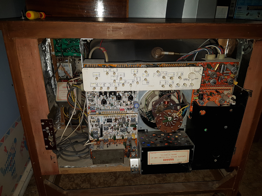 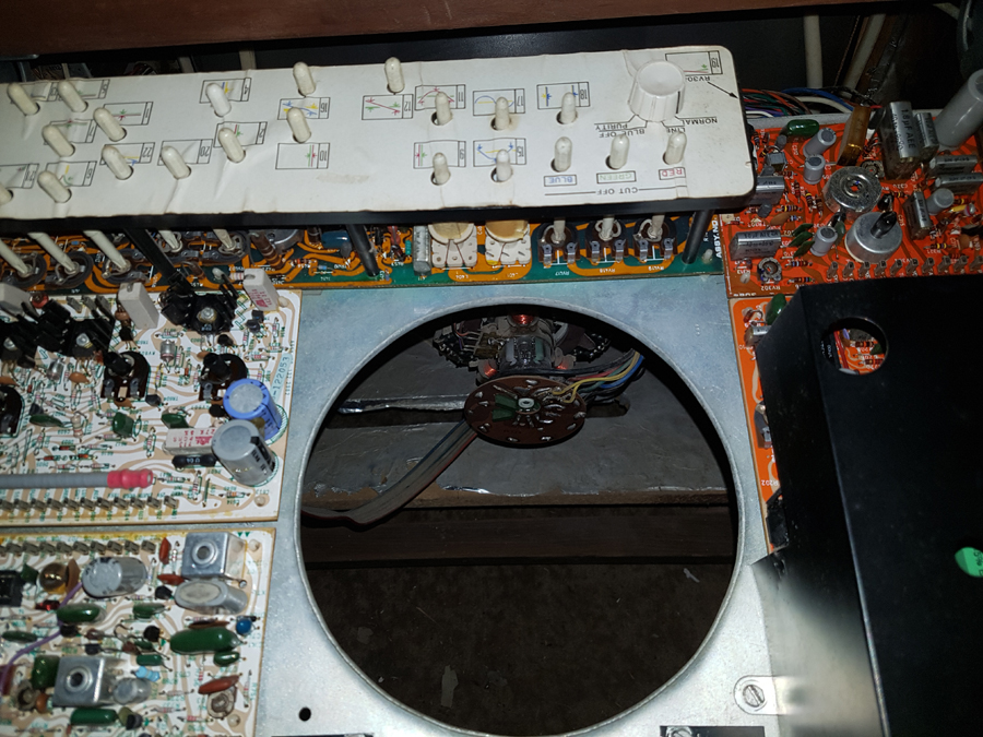 ‾‾‾‾‾‾‾‾‾‾‾‾‾‾‾‾‾‾‾‾‾‾‾‾‾‾‾‾‾‾‾‾‾‾‾‾‾‾‾‾‾‾‾‾‾‾‾‾‾‾‾‾‾‾‾‾‾‾‾‾‾‾‾‾‾‾‾‾ I love the smell of ozone in the morning. |
|
|
Return to top of page · Post #: 2 · Written at 11:40:22 AM on 7 April 2019.
|
|

|
Location: Werribee South, VIC
Member since 30 September 2016 Member #: 1981 Postcount: 485 |
|
Best of luck with the C211's. They generally were a box of faults unless all of there many ill's were sorted out. |
|
|
Return to top of page · Post #: 3 · Written at 6:39:50 PM on 7 April 2019.
|
|

|
Administrator
Location: Naremburn, NSW
Member since 15 November 2005 Member #: 1 Postcount: 7643 |
|
Photos uploaded. ‾‾‾‾‾‾‾‾‾‾‾‾‾‾‾‾‾‾‾‾‾‾‾‾‾‾‾‾‾‾‾‾‾‾‾‾‾‾‾‾‾‾‾‾‾‾‾‾‾‾‾‾‾‾‾‾‾‾‾‾‾‾‾‾‾‾‾‾ A valve a day keeps the transistor away... |
|
|
Return to top of page · Post #: 4 · Written at 7:00:27 PM on 7 April 2019.
|
|

|
Location: Albury, NSW
Member since 2 July 2017 Member #: 2134 Postcount: 181 |
|
I will be watching this restoration with a great deal of interest. |
|
|
Return to top of page · Post #: 5 · Written at 9:51:17 AM on 9 April 2019.
|
|
|
|
Location: Werribee South, VIC
Member since 30 September 2016 Member #: 1981 Postcount: 485 |
|
Their performance in fact was very good and when sorted made a very nice picture. Just not for long in many cases. |
|
|
Return to top of page · Post #: 6 · Written at 11:36:52 AM on 11 April 2019.
|
|

|
Location: Tanawha, QLD
Member since 22 December 2012 Member #: 1263 Postcount: 45 |
|
The chroma and video boards look like the ones used in the C221, C231 (Philips 20AX CRT) chassis. |
|
|
Return to top of page · Post #: 7 · Written at 8:05:34 AM on 12 April 2019.
|
|
|
|
Location: Werribee South, VIC
Member since 30 September 2016 Member #: 1981 Postcount: 485 |
|
I'd like to find a C221 or C231 as a project. |
|
|
Return to top of page · Post #: 8 · Written at 8:53:23 AM on 20 April 2019.
|
|
|
|
Location: Penrith, NSW
Member since 7 April 2012 Member #: 1128 Postcount: 405 |
|
A Tale of Two H.M.V.'s Part two of several. 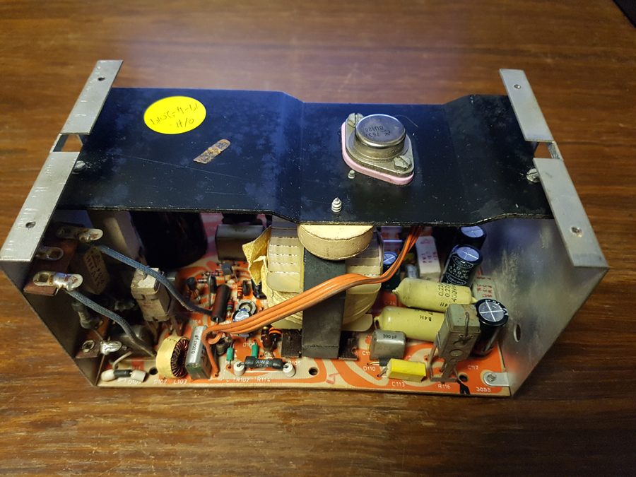 ‾‾‾‾‾‾‾‾‾‾‾‾‾‾‾‾‾‾‾‾‾‾‾‾‾‾‾‾‾‾‾‾‾‾‾‾‾‾‾‾‾‾‾‾‾‾‾‾‾‾‾‾‾‾‾‾‾‾‾‾‾‾‾‾‾‾‾‾ I love the smell of ozone in the morning. |
|
|
Return to top of page · Post #: 9 · Written at 11:18:35 AM on 20 April 2019.
|
|
|
|
Location: Werribee South, VIC
Member since 30 September 2016 Member #: 1981 Postcount: 485 |
|
Do either of the Power Supplies have the large wire wound resistors on tagstrips mounted to the side of the frame? |
|
|
Return to top of page · Post #: 10 · Written at 12:13:00 PM on 20 April 2019.
|
|
|
|
Location: Penrith, NSW
Member since 7 April 2012 Member #: 1128 Postcount: 405 |
|
Irext, ‾‾‾‾‾‾‾‾‾‾‾‾‾‾‾‾‾‾‾‾‾‾‾‾‾‾‾‾‾‾‾‾‾‾‾‾‾‾‾‾‾‾‾‾‾‾‾‾‾‾‾‾‾‾‾‾‾‾‾‾‾‾‾‾‾‾‾‾ I love the smell of ozone in the morning. |
|
|
Return to top of page · Post #: 11 · Written at 4:33:20 PM on 20 April 2019.
|
|
|
|
Administrator
Location: Naremburn, NSW
Member since 15 November 2005 Member #: 1 Postcount: 7643 |
|
Photo uploaded to Post 8. ‾‾‾‾‾‾‾‾‾‾‾‾‾‾‾‾‾‾‾‾‾‾‾‾‾‾‾‾‾‾‾‾‾‾‾‾‾‾‾‾‾‾‾‾‾‾‾‾‾‾‾‾‾‾‾‾‾‾‾‾‾‾‾‾‾‾‾‾ A valve a day keeps the transistor away... |
|
|
Return to top of page · Post #: 12 · Written at 7:32:19 AM on 24 April 2019.
|
|
|
|
Location: Penrith, NSW
Member since 7 April 2012 Member #: 1128 Postcount: 405 |
|
Hi Daro. ‾‾‾‾‾‾‾‾‾‾‾‾‾‾‾‾‾‾‾‾‾‾‾‾‾‾‾‾‾‾‾‾‾‾‾‾‾‾‾‾‾‾‾‾‾‾‾‾‾‾‾‾‾‾‾‾‾‾‾‾‾‾‾‾‾‾‾‾ I love the smell of ozone in the morning. |
|
|
Return to top of page · Post #: 13 · Written at 10:09:42 AM on 24 April 2019.
|
|
|
|
Location: Penrith, NSW
Member since 7 April 2012 Member #: 1128 Postcount: 405 |
|
A Tale of Two H.M.V.'s Part 3. ‾‾‾‾‾‾‾‾‾‾‾‾‾‾‾‾‾‾‾‾‾‾‾‾‾‾‾‾‾‾‾‾‾‾‾‾‾‾‾‾‾‾‾‾‾‾‾‾‾‾‾‾‾‾‾‾‾‾‾‾‾‾‾‾‾‾‾‾ I love the smell of ozone in the morning. |
|
|
Return to top of page · Post #: 14 · Written at 9:41:48 AM on 27 April 2019.
|
|
|
|
Location: Penrith, NSW
Member since 7 April 2012 Member #: 1128 Postcount: 405 |
|
A Tale of Two H.M.V.'s Part 4 of Several. ‾‾‾‾‾‾‾‾‾‾‾‾‾‾‾‾‾‾‾‾‾‾‾‾‾‾‾‾‾‾‾‾‾‾‾‾‾‾‾‾‾‾‾‾‾‾‾‾‾‾‾‾‾‾‾‾‾‾‾‾‾‾‾‾‾‾‾‾ I love the smell of ozone in the morning. |
|
|
Return to top of page · Post #: 15 · Written at 4:12:03 PM on 28 April 2019.
|
|
|
|
Location: Penrith, NSW
Member since 7 April 2012 Member #: 1128 Postcount: 405 |
|
A Tale of Two H.M.V.'s Part 5 of Several.  2. The tuner removed for repairs. The broken fine-tuning mechanism was a real pain to repair and took hours to get working properly. After a couple of days, I realised that after testing several lubricants for the clutch, I think that I will try “Tap Repair Grease” from Bunnings, on the other tuner, If I can find the intermediate gear. 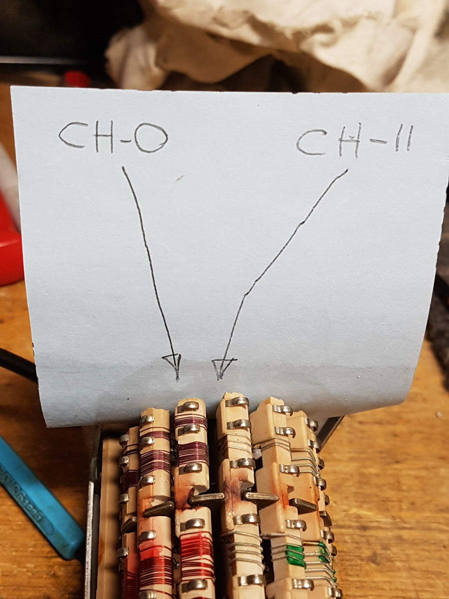 3.Note the gauge of wire and number of turns on the biscuits of the tuner. The comparison between the lower and upper ends of the tuning are easy to see. 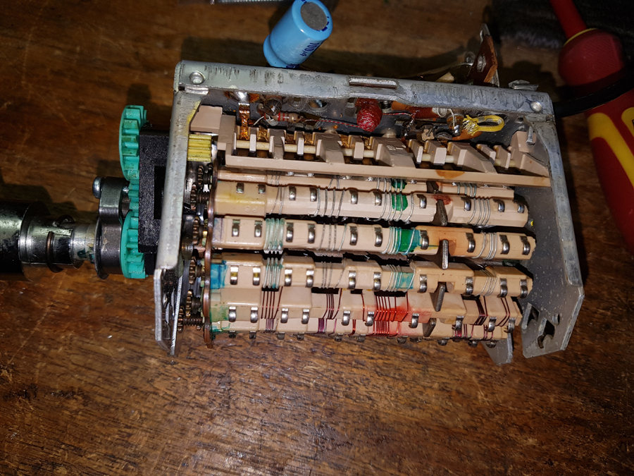 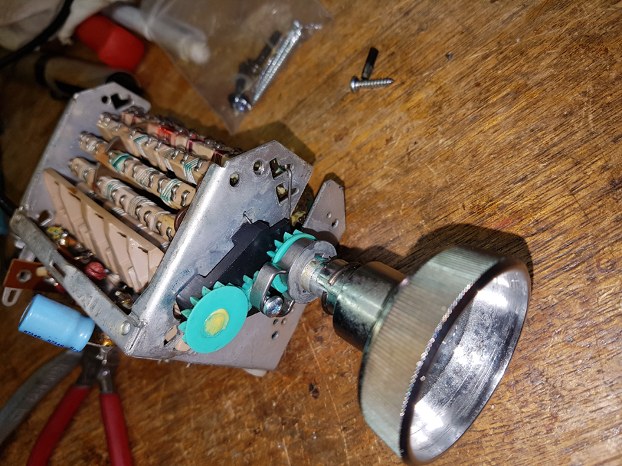 4. A few of the tools used in the repairs so far. I have not had to use a hammer just yet. We will see how it goes. 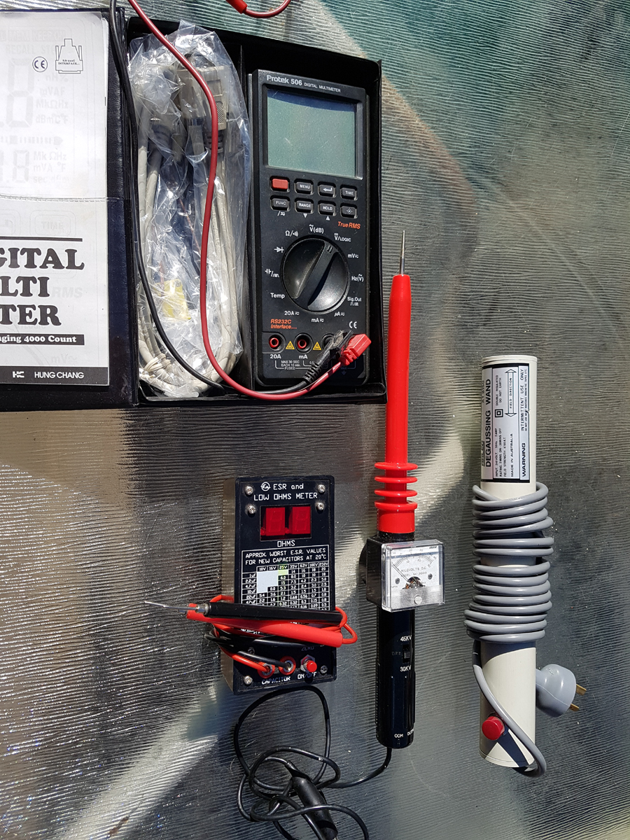 ‾‾‾‾‾‾‾‾‾‾‾‾‾‾‾‾‾‾‾‾‾‾‾‾‾‾‾‾‾‾‾‾‾‾‾‾‾‾‾‾‾‾‾‾‾‾‾‾‾‾‾‾‾‾‾‾‾‾‾‾‾‾‾‾‾‾‾‾ I love the smell of ozone in the morning. |
|
|
You need to be a member to post comments on this forum.
|
|
Sign In
Vintage Radio and Television is proudly brought to you by an era where things were built with pride and made to last.
DISCLAIMER: Valve radios and televisions contain voltages that can deliver lethal shocks. You should not attempt to work on a valve radio or other electrical appliances unless you know exactly what you are doing and have gained some experience with electronics and working around high voltages. The owner, administrators and staff of Vintage Radio & Television will accept no liability for any damage, injury or loss of life that comes as a result of your use or mis-use of information on this website. Please read our Safety Warning before using this website.
WARNING: Under no circumstances should you ever apply power to a vintage radio, television or other electrical appliance you have acquired without first having it checked and serviced by an experienced person. Also, at no time should any appliance be connected to an electricity supply if the power cord is damaged. If in doubt, do not apply power.
Shintara - Keepin' It Real · VileSilencer - Maintain The Rage