Welcome to Australia's only Vintage Radio and Television discussion forums. You are not logged in. Please log in below, apply for an account or retrieve your password.
Australian Vintage Radio Forums
  Home  ·  About Us  ·  Discussion Forums  ·  Glossary  ·  Outside Links  ·  Policies  ·  Services Directory  ·  Safety Warnings  ·  Tutorials

Vintage Television

Forum home - Go back to Vintage Television

 A Tale of Two H.M.V.'s Part one of several
« Back · 1 · 2 · 3 · Next »
 Return to top of page · Post #: 16 · Written at 10:28:58 AM on 29 April 2019.
Wirelessfan's avatar
 Location: Sydney, NSW
 Member since 26 April 2019
 Member #: 2349
 Postcount: 18

I recognise the PSU...I saw a junior tech in the process of fixing one, picking it up off the bench-unfortunately still charged-uncontrolled reflex, throwing it onto the floor, writing it off in the process!! oops!


 Return to top of page · Post #: 17 · Written at 2:36:34 AM on 30 April 2019.
Brad's avatar
 Administrator
 Location: Naremburn, NSW
 Member since 15 November 2005
 Member #: 1
 Postcount: 7301

Photos uploaded to Post 15.


‾‾‾‾‾‾‾‾‾‾‾‾‾‾‾‾‾‾‾‾‾‾‾‾‾‾‾‾‾‾‾‾‾‾‾‾‾‾‾‾‾‾‾‾‾‾‾‾‾‾‾‾‾‾‾‾‾‾‾‾‾‾‾‾‾‾‾‾
A valve a day keeps the transistor away...

 
 Return to top of page · Post #: 18 · Written at 10:12:35 AM on 8 May 2019.
Irext's avatar
 Location: Werribee South, VIC
 Member since 30 September 2016
 Member #: 1981
 Postcount: 470

Ahh the memories.
Probably the most important adjustment is the +25V rail adjustment on the Power Supply module.
Once set correctly every other supply should fall into line.
The flying leads you mention on the Hor O/P module are imperative as they bypass the PCB pins for yoke coupling etc which will fail and burn holes in the pcb.
Back in the day when changeover Hor O/P modules were available the new modules were supplied with those flying leads with utilux sockets on the ends which push on to the chassis mounted wire wrap pins thus bypassing the PCB mounted pin sockets.
The blue triplers are selenium types which can fail and if the set remains powered up with a faulty tripler long enough will cook the Line O/P Transformer.
I saw a few melted transformers due to this.
I just dragged out the C211/212 service manual for a peek and the memories came flooding back (some of them bad).
Good luck with the resto.
With a CRT that good the picies should excellent.


 Return to top of page · Post #: 19 · Written at 12:33:06 PM on 11 May 2019.
Labrat's avatar
 Location: Penrith, NSW
 Member since 7 April 2012
 Member #: 1128
 Postcount: 373

A Tale of Two H.M.V.'s Part 6 of Several.

This time I decided to tackle the poor colour problem. Armed with circuit, manual, and oscilloscope, I aligned the chroma board which is very easy. Unfortunately, the rolling noise bars of disturbance in the “chroma only” areas of the picture remained. I knew what the cause looked like, but could not see how that was possible in this design.

I could not see the disturbance on the oscilloscope, but with careful adjustment of the set's controls was able to display the offending pattern that marred the picture. The fault was present in all three channels. See the accompanying pictures and see if you can work out what the cause was. I think that most will be able to work out this one, but be warned. It is not what you think it was!

Next, I shall turn my attention to the Molex pins used throughout the set. As I am working on the set, the convergence changes. Also, I am not happy with the fact that some controls are at one end of their travel. This should not occur.

Check out the picture of the set, displaying a black and white picture. Then look to the top of the set. There you will see the chroma board. Then look at the fold up chassis and you will see a hole where the chroma board is to be plugged in. That's right. The set will work without the chroma board plugged in. This was a sales point when the sets were new. If you had a colour fault, you could watch your TV in black and white until the serviceman returned with a change over module.

There are still several faults to contend with. Slow vertical warm up, drifting convergence, controls not setting up as they should, and intermittent video/sync levels, caused by beam current limiter ?

Really, this would be considered a financial loss to any service company repairing this set, but I would not blame the set. It has been abused no end by people, whom I would not call qualified to change the batteries in a flash light.

Reply with what you think was the cause of the disturbance in the coloured areas of the picture.
I shall reveal the cause in my next posting.


Wayne.

HMV Television
HMV Television
HMV Television
HMV Television


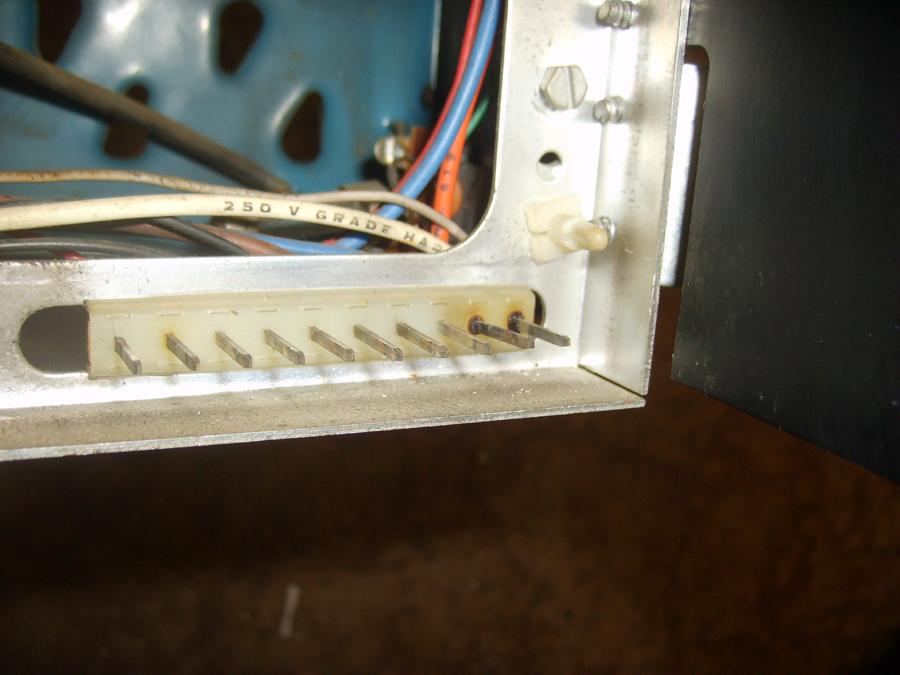
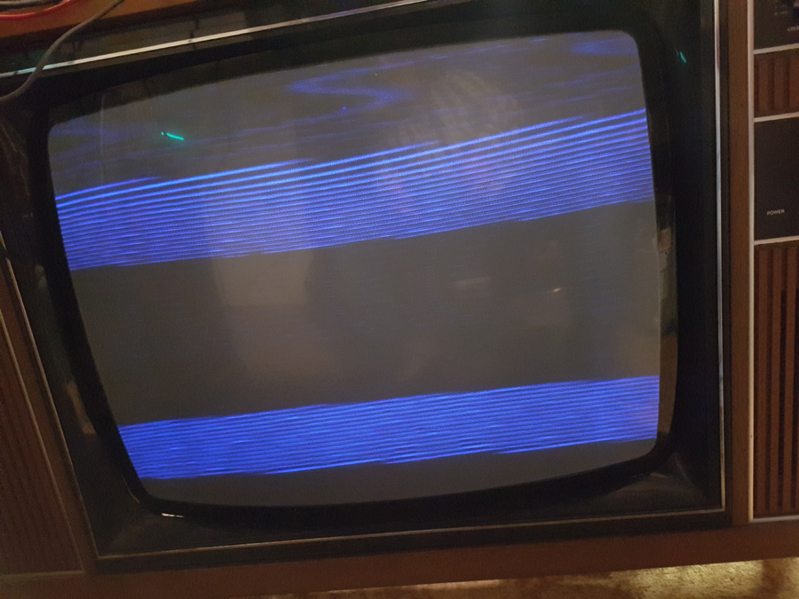
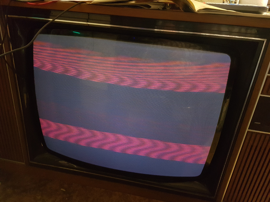
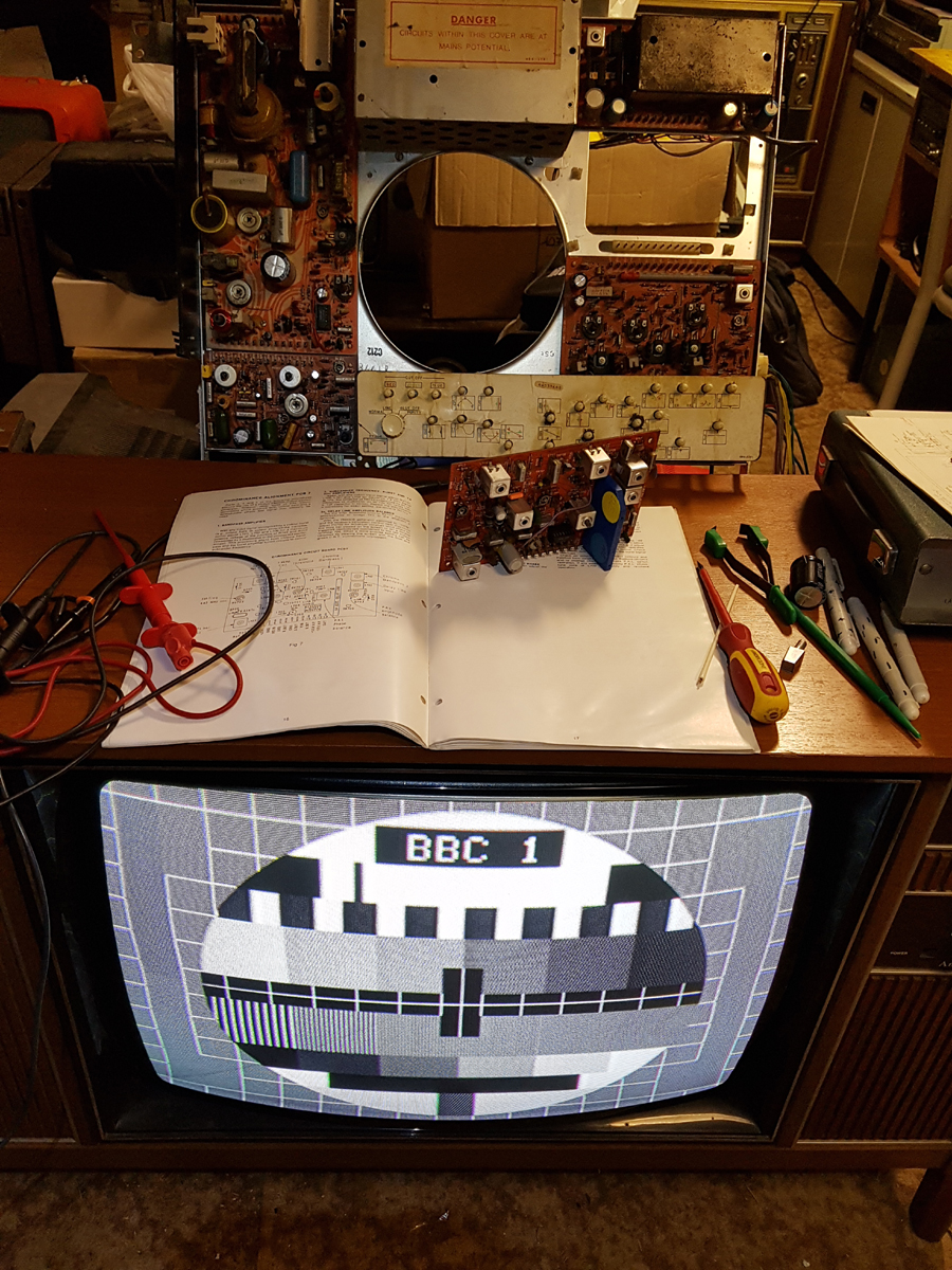
 Return to top of page · Post #: 20 · Written at 8:46:55 AM on 12 May 2019.
Irext's avatar
 Location: Werribee South, VIC
 Member since 30 September 2016
 Member #: 1981
 Postcount: 470

Youv'e got my interest now.
Pictures haven't been included as yet but I'll chuck in my 2 cents worth when I see them.
I thought i'd seen just about every fault a C211/212 could throw at me but I guess some of the ones you are seeing could be age related.
If I recall correctly there were some mods to the convergence board to minimise drift but my memory of what they were has long since been erased.


 Return to top of page · Post #: 21 · Written at 2:12:00 PM on 12 May 2019.
Brad's avatar
 Administrator
 Location: Naremburn, NSW
 Member since 15 November 2005
 Member #: 1
 Postcount: 7301

Photos uploaded to Post 19.


‾‾‾‾‾‾‾‾‾‾‾‾‾‾‾‾‾‾‾‾‾‾‾‾‾‾‾‾‾‾‾‾‾‾‾‾‾‾‾‾‾‾‾‾‾‾‾‾‾‾‾‾‾‾‾‾‾‾‾‾‾‾‾‾‾‾‾‾
A valve a day keeps the transistor away...

 
 Return to top of page · Post #: 22 · Written at 8:39:22 AM on 13 May 2019.
Irext's avatar
 Location: Werribee South, VIC
 Member since 30 September 2016
 Member #: 1981
 Postcount: 470

Looks like a supply filtering issue to me or at least that's where I would start looking with a CRO.
Those burnt pins were a well known problem on the Hor scan board pins.
The fix was to bypass them with flying leads with female utilux pins on the ends which push on to the wire wrap pins.
The C211 had a quite low HV supply due to the scan SCR rating and thus had fairly high Hor Scan current which ate the pcb pins.
The yoke although it looks just like a Philips K9 yoke is a low impedance version and not interchangeable.
The C211 was a very ambitious design borrowing heavily from European designs, ie Hor Scan borrowed from Blaupunkt/Korting, power supply from Luxor etc.
Problem was in the implementation and quality control.
However capable of very good performance when beaten into shape.


 Return to top of page · Post #: 23 · Written at 5:24:58 PM on 4 June 2019.
NickyD's avatar
 Location: Erskineville, NSW
 Member since 5 July 2018
 Member #: 2261
 Postcount: 10

Hi Wayne,
It is such a delight to see that you’re fixing up the old Consulate I sold you. I look forward to your future posts and I can now see that I would have never been able to get it running myself.


 Return to top of page · Post #: 24 · Written at 2:44:31 PM on 15 June 2019.
Labrat's avatar
 Location: Penrith, NSW
 Member since 7 April 2012
 Member #: 1128
 Postcount: 373

A Tale of Two H.M.V.'s. Part 7 of Several.


Hello all.
The saga continues. I've been having problems with differing results with different signal sources.

Signal source No.1
Off air signal from a set top box output to composite, fed to a V.H.F. Modulator on Ch-1.

Signal source No.2
A D.V.D. Player output to composite, fed to a V.H.F. Modulator on Ch-2.

Signal source No.3
Philips Generator PM 5509
R.F. Output on Ch-1.

Pattern on screeen


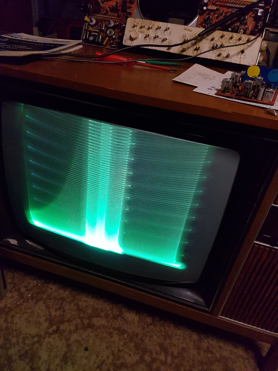
The problem/challenge, is, if I set up the chroma board on one source it will work well on that source, but will have no colour then receiving another source.

After much back and forth, I discovered that if the set were aligned using the Philips pattern generator, (which is the one specified in the service manual), the chroma board the chroma would accept all signals. But ! One must use the more detailed alignment procedure and not the simple method listed.

I have had much fun chasing leaking caps, two of the three G2 filters were breaking down, not going short, but their resistance followed the “roller coaster” trajectory, a faulty I.F. Integrated circuit, Burst blanking faults, convergence faults, and, apparently, some errors in the service manual. Then there were quite a number of electros to be changed. Oh, and the scan board decided to quit on me while I was chasing other faults. You will love the picture when it is posted. Reminds me of a Spirograph.

Thank goodness I have two sets here to work with. Shudder, I just remembered that the other set has a broken fine tuning mechanism.

Back to reality. I have found reading the schematic for the set rather difficult. Checking with a steel ruler, I've ascertained the size of the text to be 1mm in height.
Not a problem when I was younger, but now in my 60's quite another matter.

The earlier set had has a “plague,” of AEE caps fitted. The last off the line, almost none.

The The double ended Ambassador set looks quite good now. It is still using the scan board from the newer set and has one more fault to fix. Both sets get a kind of video smear whenever the contrast control is advanced too high. Only happens when fed the off air signal through the modulator.

Any way. I'm off to Jaycar, to get another “fist full of caps” and a replacement for R233.

There are still no takers for the reason for the pattern in the chroma only areas of the picture colour?


 Return to top of page · Post #: 25 · Written at 9:00:05 AM on 17 June 2019.
Irext's avatar
 Location: Werribee South, VIC
 Member since 30 September 2016
 Member #: 1981
 Postcount: 470

I did offer one possible reason previously but it sounds too easy. Supply filtering??


 Return to top of page · Post #: 26 · Written at 5:04:59 PM on 17 June 2019.
Labrat's avatar
 Location: Penrith, NSW
 Member since 7 April 2012
 Member #: 1128
 Postcount: 373

Hi Irext.

You are correct. But it goes further.

C711, was missing. It filters the chroma control line. The odd thing is that the interference is obviously 100Hz but where does it come from? the power supply is running at around 23kHz.

Another one for the X Files. The explanation is out there somewhere.

Regards

Wayne


 Return to top of page · Post #: 27 · Written at 8:30:40 PM on 17 June 2019.
Brad's avatar
 Administrator
 Location: Naremburn, NSW
 Member since 15 November 2005
 Member #: 1
 Postcount: 7301

Photo uploaded to Post 24.


‾‾‾‾‾‾‾‾‾‾‾‾‾‾‾‾‾‾‾‾‾‾‾‾‾‾‾‾‾‾‾‾‾‾‾‾‾‾‾‾‾‾‾‾‾‾‾‾‾‾‾‾‾‾‾‾‾‾‾‾‾‾‾‾‾‾‾‾
A valve a day keeps the transistor away...

 
 Return to top of page · Post #: 28 · Written at 5:32:02 PM on 21 July 2019.
Labrat's avatar
 Location: Penrith, NSW
 Member since 7 April 2012
 Member #: 1128
 Postcount: 373

A Tale of Two H.M.V.'s

One down, one to go.

Hi Folks. Finally an up-date on the long running saga of the H.M.V.'s.

I have finished off the double ended Ambassador 26. There is one last fault that I do not care to chase, and is only present whenever the contrast control is up high on off air material.

I now have all the metal covers in place, and, believe it or not, the set operates as silent as if it were not switched on.

I guess you would like to know what was wrong with it ? It is probably easier to say what was right with it. Some of the things that required attention were the tuner's broken fine-tuning mechanism and the dirty contacts, the blown up power supply, with a wrong type transistor fitted. The convergence panel with broken pot and leaky capacitors. The shorted thyristor in the horizontal output. Missing resistor in the linearity circuit. Missing capacitor in the colour control line. A problem with the burst blanking. The service switch not working as it should have. Slow vertical warm up. Chroma board unstable.

You get the idea. But the picture is wonderful. The set looks lovely. Now that it has the covers on, it really looks the piece of furniture in a way that no panel on the wall T.V. can. I am really surprised at how good it looks. It has been so long since we had such lovely furniture as this. The plastic sets of the 1980's and 90's whether they were silver, black, or even white, could not make themselves look good. One had to look at the picture to distract one's self from the ugliness of the modern T.V.

The tally, as best I can work out for the Ambassador, is seventeen caps, twenty electrolytic caps,
two diodes, one trim pot, two resistors, one thyristor, one transistor, and many hours spent chasing faults that came and went, and varied in symptoms. I guess one can only clean and retention the Utilux pins, and their accompanying sockets so much. I would dearly loved to have been able to replace them.


Wayne.

HMV Ambassador Valve Television


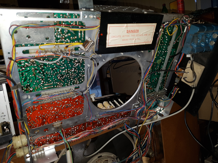
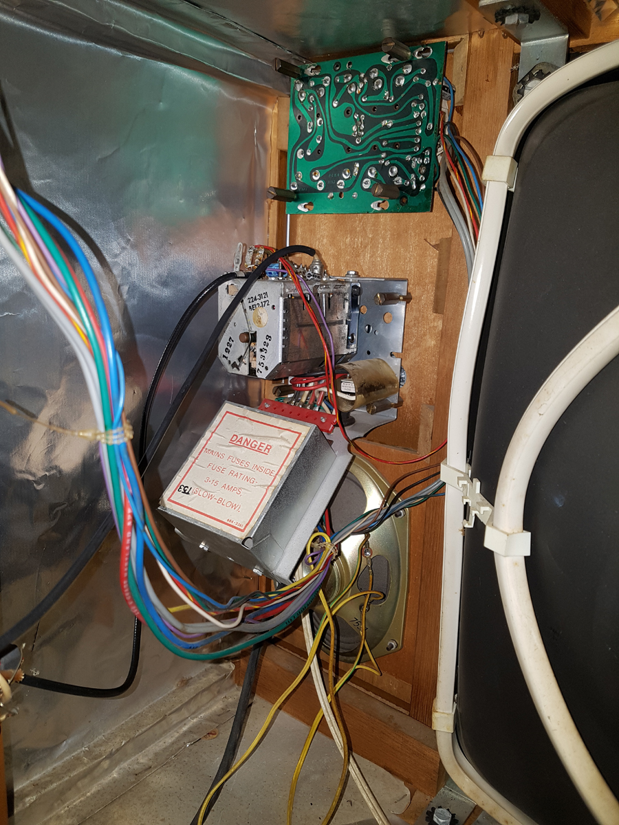
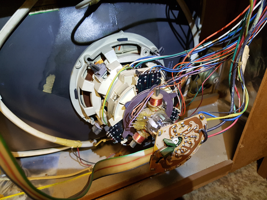
 Return to top of page · Post #: 29 · Written at 10:45:25 AM on 22 July 2019.
Irext's avatar
 Location: Werribee South, VIC
 Member since 30 September 2016
 Member #: 1981
 Postcount: 470

Well done Wayne. Where did you source the scan thyristor?
I can't imagine them being a stock part anywhere these days.
With the Utilux pins your best friend would be Deoxit for most of them and bypass for the ones carrying scan current.
They must have seemed like a great idea at the time but caused no end of trouble in the field.
Those AEE caps were a fire waiting to happen.
I remember foolishly folding a chassis down one day while the set was on and one in the power supply burst into flames in front of me!
Aussie caps weren't much good I'm afraid.
As you say the cabinets were something special.
My favourite was the Consulate which you have (a teeny bit jealous).


 Return to top of page · Post #: 30 · Written at 9:29:11 PM on 27 July 2019.
Brad's avatar
 Administrator
 Location: Naremburn, NSW
 Member since 15 November 2005
 Member #: 1
 Postcount: 7301

Photos uploaded to Post 28.


‾‾‾‾‾‾‾‾‾‾‾‾‾‾‾‾‾‾‾‾‾‾‾‾‾‾‾‾‾‾‾‾‾‾‾‾‾‾‾‾‾‾‾‾‾‾‾‾‾‾‾‾‾‾‾‾‾‾‾‾‾‾‾‾‾‾‾‾
A valve a day keeps the transistor away...

 
« Back · 1 · 2 · 3 · Next »
 You need to be a member to post comments on this forum.

Sign In

Username:
Password:
 Keep me logged in.
Do not tick box on a computer with public access.