Welcome to Australia's only Vintage Radio and Television discussion forums. You are not logged in. Please log in below, apply for an account or retrieve your password.
Australian Vintage Radio Forums
  Home  ·  About Us  ·  Discussion Forums  ·  Glossary  ·  Outside Links  ·  Policies  ·  Services Directory  ·  Safety Warnings  ·  Tutorials

Wanted and For Sale

Forum home - Go back to Wanted and for sale

 Transformer for Kriesler 11-81 Panorama wanted
« Back · 1 · 2 · 3 · 4 · 5 · Next »
 Return to top of page · Post #: 1 · Written at 8:22:06 AM on 16 June 2018.
Muzzery's Gravatar
 Location: Maleny, QLD
 Member since 28 February 2018
 Member #: 2218
 Postcount: 95

Hello,
Before I look into having the main power tranny sent away for rewinding, I wonder if anyone has one in working condition willing to sell?
Kind regards, Murray


 Return to top of page · Post #: 2 · Written at 8:45:37 AM on 16 June 2018.
Johnny's avatar
 Location: Hobart, TAS
 Member since 31 July 2016
 Member #: 1959
 Postcount: 544

Are you sure the power transformer is faulty.
Unless of course rodents have eaten it.
Have repaired 100’s of this model, and never a faulty power transformer.
Give us some more details.
I have a whole chassis that I purchased for $5, but postage would be prohibitive.
JJ


 Return to top of page · Post #: 3 · Written at 11:59:43 AM on 16 June 2018.
Muzzery's Gravatar
 Location: Maleny, QLD
 Member since 28 February 2018
 Member #: 2218
 Postcount: 95

Hi Johnny,
I AM very new to this game, and its all very new to me. Its possible I am barking up the wrong tree..

I received it as a non working "parts" radio from a fellow I did some building work for. He had powered it up , replaced all the valves, and possibly cooked the tranny. it had a large pool of molten wax underneath it. I have since gotten the old chap a dim bulb tester of his own..

So far, have recapped this radio, paper and electrolyte.It powered up ok on dim bulb tester.

It made a little static through the speaker, but no stations.
He had given me the old valves with it, so I had swapped all out, to see if one is dead. no improvement, however I found he had two valves in the wrong place.


I spoke to a few persons to learn about testing the tranny.. I don't yet fully grasp the layout of the tabs (6) on the tranny. I was directed to remove the rectifier valve, and measure pin 1, & pin 7 , which read read around 250v. The schematic shows 245.
The dial lights work, so that 6.3 volt coil must be ok- I would need to remove dial lamps and all valves to measure that voltage I think?
The top right tab on the tranny as in the photo ( I will ask Brad to attach) has two electrolytic caps, (I put 2 in Parallel to make the capacitance value) which go to tab 3 of rectifier valve. This reads zero volts. I suspect that winding is cooked perhaps. ( readings are taken from earth, to respective point, Is this correct?)
It was this last measurement of pin 3 of rectifier, that makes me think tranny is damaged.

It may also be a dodgy resistor, this is my next learning curve, check / replace resistors.
Murray


 Return to top of page · Post #: 4 · Written at 12:11:39 PM on 16 June 2018.
Muzzery's Gravatar
 Location: Maleny, QLD
 Member since 28 February 2018
 Member #: 2218
 Postcount: 95

https://www.radiomuseum.org/schemaviewer/aus_Kriesler_11_81_sch1.pdf
Here is the schematic,

Is it possible that tab in question should be the -13 volts? ( Is that a Grid bias?)
Murray


 Return to top of page · Post #: 5 · Written at 12:30:31 PM on 16 June 2018.
Johnny's avatar
 Location: Hobart, TAS
 Member since 31 July 2016
 Member #: 1959
 Postcount: 544

Sounds like the power transformer has been stressed, but may be OK.
What is the resistance from both pins 1 and 7 to earth. Should be a low value, which is part of the center tap bias arrangement.
Measure the resistance from pin 3 to earth, leaving the test meter connected for a while to allow for the electro effect.
Assume you have replaced the rectifier valve.
Not a good idea to do a total recap without prior diagnostics.
However in this model the cap to earth on the plate of the output valve needs replacing as does the coupling cap to G1 of the same valve.
Someone on this forum would describe this as being got at by monkeys and I think it may have.
Please report back with what I’ have asked.
JJ


 Return to top of page · Post #: 6 · Written at 9:40:19 AM on 17 June 2018.
Muzzery's Gravatar
 Location: Maleny, QLD
 Member since 28 February 2018
 Member #: 2218
 Postcount: 95

Johnny,
Thanks for the direction. I tested earth to pin 1, and earth to pin 7. Both read around 660k.
Pin 3 to earth reads infinite.

I am using an analogue meter, and still learning to read it! A digital meter is on my wishlist.
I will quite happily be called a monkey.. but hopefull to be working my way up the "vintage radio repair monkey to human scale" Smile


 Return to top of page · Post #: 7 · Written at 11:47:54 AM on 17 June 2018.
Johnny's avatar
 Location: Hobart, TAS
 Member since 31 July 2016
 Member #: 1959
 Postcount: 544

OK, There is your first problem.
Pins 1and 7 should measure around 300 ohms to earth.
This means the 270 ohm( not sure of model). From the centre tap of the secondary winding to earth is open circuit.
It should be a fairly large resistor and should be easy to find as the first filter electro’ s negative goes straight to it.
Replace the resistor, fire up with dim bulb tester and let us know.
Monitor rectifier pin 3 as it fires up.
The mains transformer still may have damage, but we will get to that later.
JJ


 Return to top of page · Post #: 8 · Written at 1:02:13 PM on 17 June 2018.
BringBackTheValve's Gravatar
 Location: Linton, VIC
 Member since 30 December 2016
 Member #: 2028
 Postcount: 467

Hello Muzzery,

I would never call you a monkey, bearing in mind that most folks here started life with analogue meters. Sure, DVM's are wonderful devices
and quite essential in modern electronics, but the good old analogues still find their niche. I often use my analogue meter with valve equipment testing, especially when the digital meter becomes confused measuring a poorly-filtered B+ rail, for example.

when you get around to obtaining your digital meter, hold onto your analogue meter, I'm sure you won't regret keeping it.

Cheers,

G.


 Return to top of page · Post #: 9 · Written at 1:48:59 PM on 17 June 2018.
Gandhn's Gravatar
 Location: Cameron Park, NSW
 Member since 5 November 2010
 Member #: 770
 Postcount: 387

If you measure resistance from pin 1 to pin 7 on the rectifier, you should see some 50 to 100 ohms. This will tell you if the winding is intact and if it is, the 270 ohm resistor is suspect, as Johnny suggested.

I concur with the comment re analogue meters, in many cases, a digital meter will read much higher than a 1000 ohm per volt analogue meter and the 11-81 circuit specifies such a meter for testing.

Harold


 Return to top of page · Post #: 10 · Written at 3:11:14 PM on 17 June 2018.
Ian Robertson's Gravatar
 Location: Belrose, NSW
 Member since 31 December 2015
 Member #: 1844
 Postcount: 2369

Kriesler were one of very few manufacturers to use wax on mains transformers. It was quite common to see wax dripping out of a transformer without it being bad. I have never encountered a bad example of these transformers.

If your dim bulb says it's OK, it's OK (at least as far as shorted turns are concerned). Like others have said, it's been stressed due to a fault but it has probably survived.


 Return to top of page · Post #: 11 · Written at 9:58:16 PM on 17 June 2018.
Muzzery's Gravatar
 Location: Maleny, QLD
 Member since 28 February 2018
 Member #: 2218
 Postcount: 95

Johnny,
After an excursion to Jaycar today, I have replaced the 270 ohm resistor , running from transformer to earth. It was large, as you said,. This might be a bit clearer when photo is uploaded. (I will go and see if I'm sending photos to Brad's correct address now!)

I measured the old 270 at 360 ohms after I removed it.

Pin 1 now reads infinite ohms, 270 volts to earth.
Pin 7 says 500 ohms,180 volts to earth
Pin 3 said 370 ohms. then I fired it up, now it reads between 1800 ohms and infinite ohms. around 380 volts pin to earth. it has new 32mf electro running off it, back to transformer. (two paralell 16mf)

I swapped out for another valve, all read similar.

Murray
edit - Incidentally, both valves that I have, infinite resistance pin 1 to pin 7. is this a "forehead slap " moment?

Kriesler 11-81 Chassis


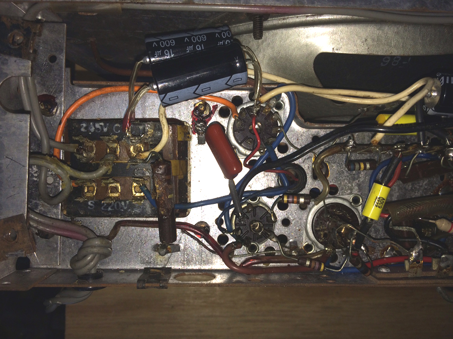
 Return to top of page · Post #: 12 · Written at 10:08:32 PM on 17 June 2018.
Brad's avatar
 Administrator
 Location: Naremburn, NSW
 Member since 15 November 2005
 Member #: 1
 Postcount: 7300

Photo uploaded to Post 11.


‾‾‾‾‾‾‾‾‾‾‾‾‾‾‾‾‾‾‾‾‾‾‾‾‾‾‾‾‾‾‾‾‾‾‾‾‾‾‾‾‾‾‾‾‾‾‾‾‾‾‾‾‾‾‾‾‾‾‾‾‾‾‾‾‾‾‾‾
A valve a day keeps the transistor away...

 
 Return to top of page · Post #: 13 · Written at 10:19:36 PM on 17 June 2018.
Johnny's avatar
 Location: Hobart, TAS
 Member since 31 July 2016
 Member #: 1959
 Postcount: 544

The photo wiring appears to be correct.
Negative of filter cap to centre tap and one end of the resistor.
If you are getting around 300 volts positive(DC) on pin 3, then the rectifier is working.
Provided no other major faults should hears sounds out of it.
JJ


 Return to top of page · Post #: 14 · Written at 1:23:20 AM on 18 June 2018.
Robbbert's avatar
 Location: Hill Top, NSW
 Member since 18 September 2015
 Member #: 1801
 Postcount: 2012

Edit...


 Return to top of page · Post #: 15 · Written at 8:52:40 AM on 18 June 2018.
Johnny's avatar
 Location: Hobart, TAS
 Member since 31 July 2016
 Member #: 1959
 Postcount: 544

If that’s a .0047 cap on pin 6 of the 6AQ5 it should be on pin 5. (The dangers of doing a total recap by newbies).
Also measure DC voltage at pin 5( thin blue wire from speaker transformer)
Should be 200 odd volts.
Please report back with this info only. I’m assuming you have a circuit.
JJ


« Back · 1 · 2 · 3 · 4 · 5 · Next »
 You need to be a member to post comments on this forum.

Sign In

Username:
Password:
 Keep me logged in.
Do not tick box on a computer with public access.