|
Kriesler beehive information schematic
|
|
|
|
|

|
Location: Central Coast, NSW
Member since 18 April 2014
Member #: 1554
Postcount: 215
|
|
|
|
|
|

|
Location: Melbourne, VIC
Member since 20 September 2011
Member #: 1009
Postcount: 1182
|
|
|
|
|
|
|
|
Location: Central Coast, NSW
Member since 18 April 2014
Member #: 1554
Postcount: 215
|
Got a photo coming when Brad gets the time..
(I'll email it to if you like)
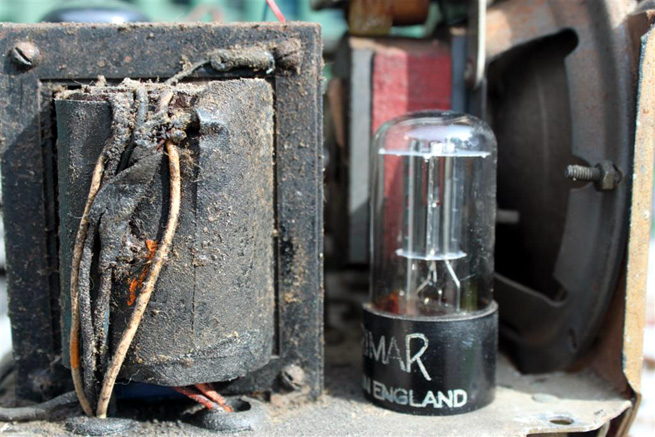
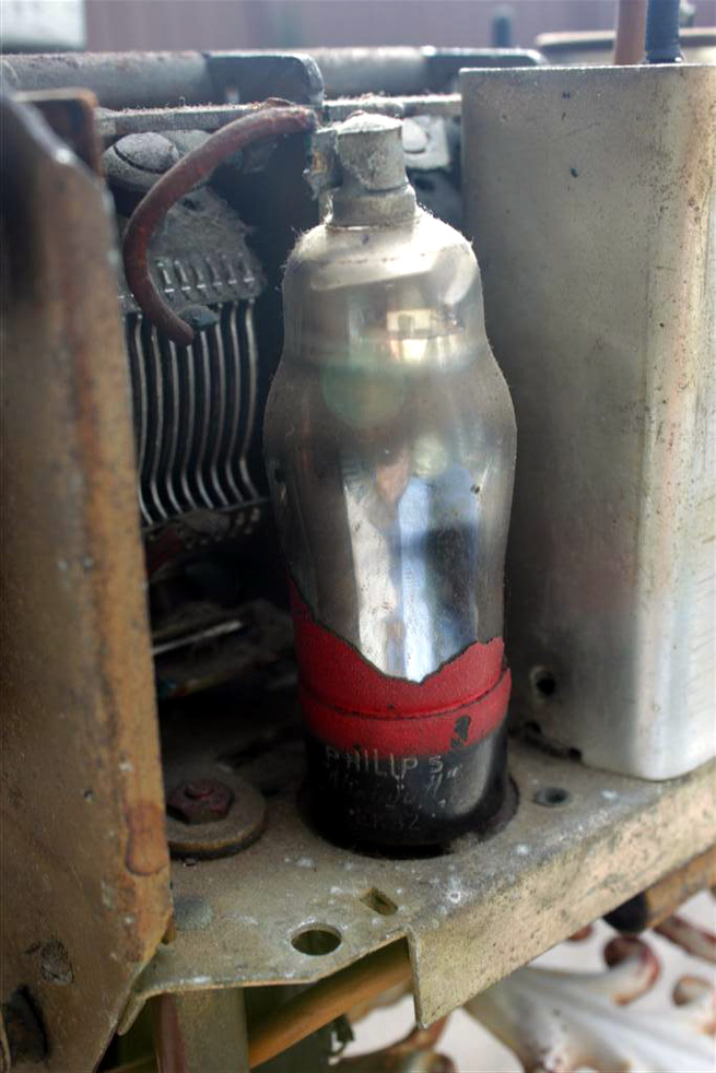
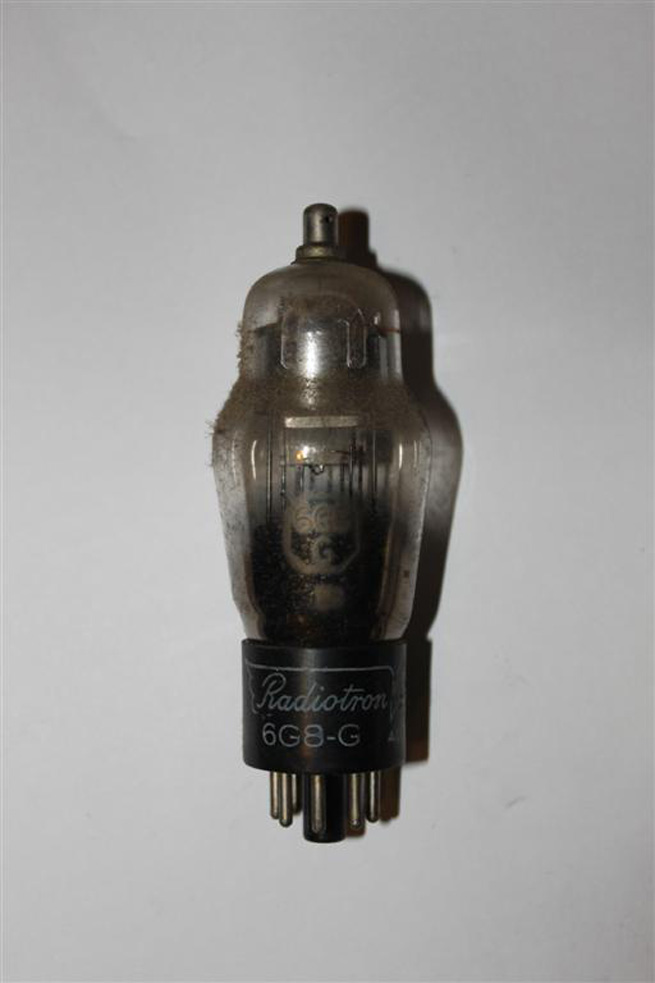
it says Phillips "milliwatt" EK32 on the base of the tube
the 3 a bit smudged
Thanks for the Doc 
PS
if it was stamped on the red shield paint only ... its long gone
actually on the speaker ..and oops I didnt include a shot DOH!
(now send Brad another so you can see it)
you can see part of it behind the Rec Valve
see photos above
that might give you a clue as to wast it is..cause I got no idea..it makes noses and for that at lest I am happy..
|
|
|
|
|

|
Location: Wangaratta, VIC
Member since 21 February 2009
Member #: 438
Postcount: 5257
|
Electrodynamic speakers a quite distinct. Unlike the modern speakers with a permanent magnet, it will often have four to five wires, whereas, the permag will have two wires to the speaker transformer (if on speaker).
If the paperwork on the back of the electrodynamic is OK, then it will have a field coil resistance 1500 for 5" spkr 70-1 printed on it.
There will be circuit changes for EK2 (Octode) from 6J8 & ECH35 (Triode Hexode).
The paperwork I have seems clearer than what appears on Kevins site. I might send it to him.
Marc
|
|
|
|
|
|
|
Location: Central Coast, NSW
Member since 18 April 2014
Member #: 1554
Postcount: 215
|
Thanks Marcc
this thing from what little I can follow of it, if right is all over the place like a dogs dinner
The rectifier Heater if pin 7 is the other side goes to ground like straight to chassis
pin 2 of the 6V6 goes back to the rectifier 6X5 pin 2
sshh no wonder you weren't impressed with them
thought I think your were talking in relation to a 5Y3 rectifier, which is a different arrangement
I guess the wiring is different since there no 5 volt
winding and it all comes from the 6V3 for the heaters filaments
Current draw for the Heater of the 6X5 is 600 mA (0.6 Amp)
I haven't found were the other side of the 6V3 winding is
but seems it decked somewhere
----
Edit: Goes to Deck near were it pops through the grommet
Chassis is the Heater return path...rather interesting
---
on the Speaker ...there is a red and blue on the primary
and I see a green and black that seems to go the speaker coil..that not conclusive thought just form what I can see so it kind look like a single ended Audio amp stage
thats from what I know of guitar tube amps
its going to be a fun circuit to chase out
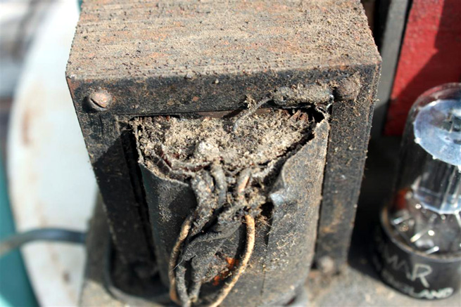
My biggest worry is that the main transformer thought maybe not cooked has been cooking well over time it appears
Gee dont you love the mounting "twisted metal"
Anyway this is looking more like rebuild then refurb
think I'll wait till the photos go up for your opinions on this puppy
EDIT
--------
Thanks Brad there up people
(and what Have I gotten myself into)
-------
long term project I think looking at it
looks like i'll be replacing most all of the caps and resistors...
but the big questions are on the transformer and IF cans
tuning gang too I suppose ..sure it works ok as far as plates go but travels not right
anyway enough for one night I think but thanks again for the help
Cheers
|
|
|
|
|
|
|
Location: Wangaratta, VIC
Member since 21 February 2009
Member #: 438
Postcount: 5257
|
Observations:
Philips Octode so you need the mods for that.
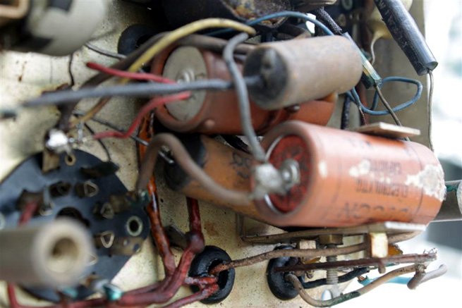
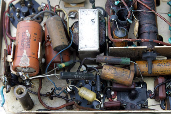
It has paper caps, they have to go. The electrolytic's have to go
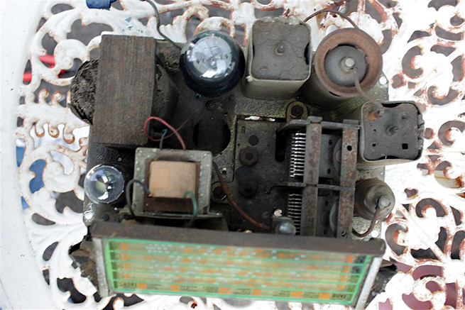
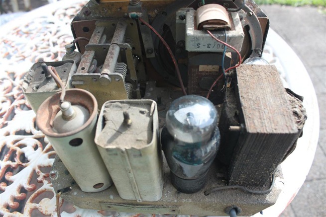
With a red block like that Magnavox its Permanent magnet, thats why that transformer looking thing in the middle of the pan, is a choke.
The disentry coloured cap should be ok but check it for cracks in its jacket.
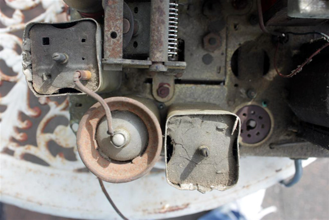
The set was in the kitchen: That crap is stuck on with fat. Do not rub the number side of the dial. Vacuum cleaner & brush is a good start.
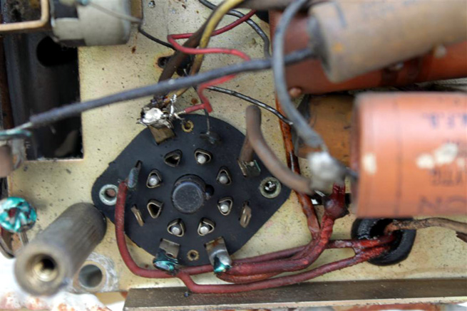
You can see that someone has had a go at it, by the new cap & the joints missing the green paint.
Definitely a shielded transformer.
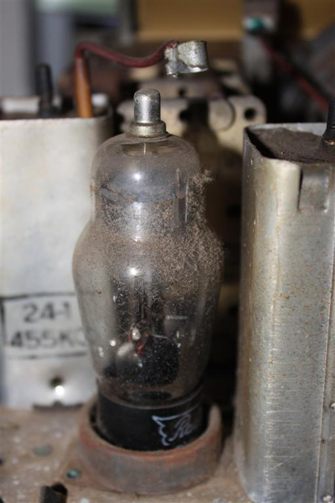
Lever the grid clamp of by twisting a lever between it and the edge of the metal of the top cap to avoid removing the cap at the glass also lever assist valve removal rather than put stress on the glass to base bond. critically important with the metalised valve.
|
|
|
|
|
|
|
Location: Central Coast, NSW
Member since 18 April 2014
Member #: 1554
Postcount: 215
|
Thanks Marc
I'll get back to you soon
just got to go out.
Back
oh opps Mod yes please were do I find them ?
OK yeah the output transformer is a replacement
as is the Cap I think you talking about across the 6V6
I am sure it suffered the fail mode you referred to sometime in the mid 60's
still for the price of a cap it can go too
I did think about levering out the EK32
but thought I might crack the base so as gently as possibly in a circular motion on the base worked it out
Sadly as to be expected with vavles 70 odd years old
even thought I gently used a flat head screw driver to remove the Cap connector..it seem well designed to take the pressure of and raise the connector at the same time...
I was pinning the cap to the tube with my finger, still the glue gave way
it still attached just loose
So Question if you dont mind
what is the best or safest way to reattach the cap and bases of Valves?
Sorry for yelling Id use colour but no option for that
I've read clear Nail polish and a zillion other ideas too
the base of the 6G8G and 6V6 think also the 6X5 have l broken loose ...I was kinda expecting that anyway
even thought all due care was used
(I am well aware of not using the bottles to pull them)
I am trying to get replacements for the RF IF vales anyway but hens teeth might be easier to find as new
got a 6X5 coming (just in case) and 6V6s are not a problem really
At the moment trying to document what connects were for future reference...photos are good but so much is hidden and get a part list together
still I do have many questions
My biggest worry is what the best way to go wit the IF Cans..?
leave them alone and just heat shrink and maybe humm put some sleeving stuff over the wire that goes to the 6G8G or are they possible to rebuild...? with out too much hassle...doubt after all this time they'd be adjustable if need be
Ditto the mains transformer
I was thinking of heat shrinking and ..whats it call spaghetti tubing? the wires for safety
Aslo of possibly removing it and giving it a light wire brushing of the E I Core and painting it with black enamel engine paint (and after giving it a work out that is)
there is corrosion and EI laminations dont work too well as one big metal mass
yes a tentative move to stave off something I know
I know some times things are best left alone and sure thats my worry... the fragility of everything with this after 70 odd years
I dont want to touch the top of the coils for fear of losing any enamel and the it would be all over red rover for that tranny if I get shorted turns
=========================================
I Have Edited out the info here for anybody that may have read it before...would only confuse the Situation leaving it in
I have now done some chasing out and discovered probably what killed the set
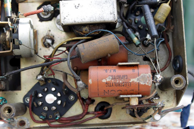
First off, there are 2 X 8μF Electrolytic Capacitors rated at 600V Ducons
**
THIS ABOUT "PI" IS QUITE WRONG PLEASE READ MARC's COMMENT BELOW ITS IMPORTANT
WRONG The configuration as near as I can tell is a PI Filter of the 6X5 Rectifier Valve WRONG
**
I suppose 2 X 10 μF 500 V will do the Job but I truly need to check the Transformer Voltages and even if it still works
Now the Big Clanger
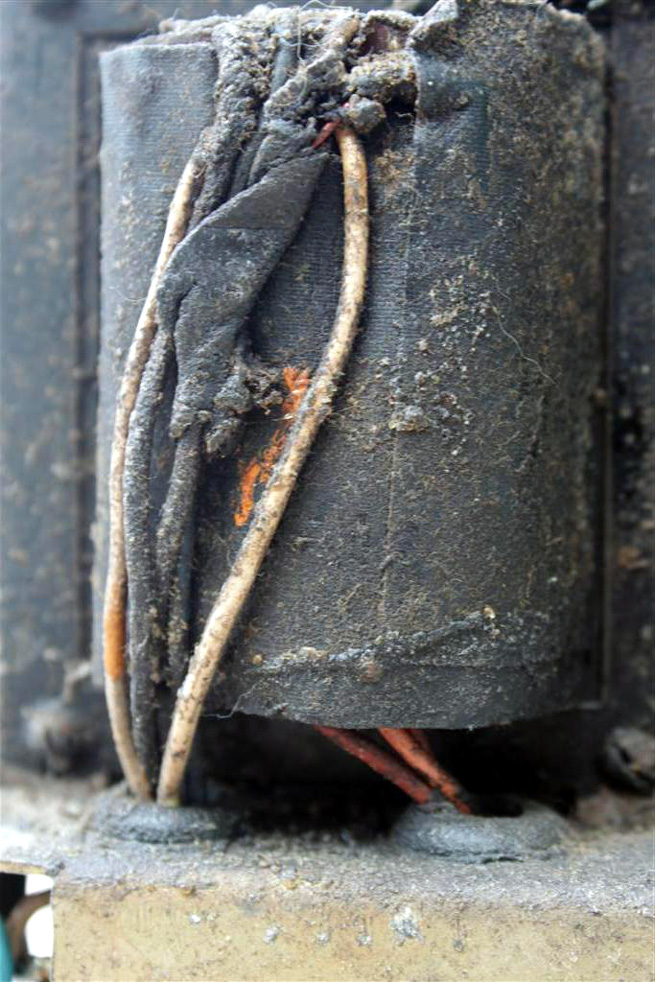
Under the bottom cap it appears there was a heater wire, it look as if it was shorting to the Chassis
(it was the feed from 6V6 to the 6X5, Transformer goes to the 6V6 first... if memory serves)
Since the Chassis was the return path for the 6V3 Heater winding I am guessing "its good night Irene" for the Transformer
nothing like a short circuited winding to spoil your Day 
Sadly no fuses in this thing
====================================
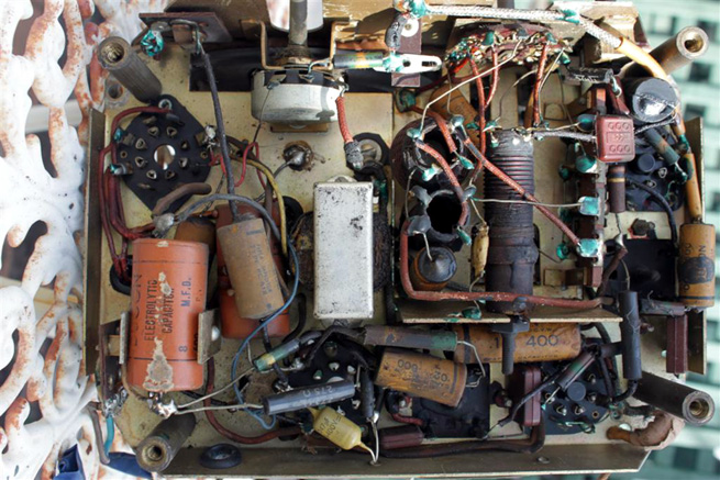
lastly.... thought I haven't checked the Docs, But it looks like there has been some work on the EK32 socket...green paint missing and the 100K (I think) is not as old the other resistors
Anyway this is proving to be quite a learning experience for me, Thanks people
|
|
|
|
|
|
|
Location: Melbourne, VIC
Member since 20 September 2011
Member #: 1009
Postcount: 1182
|
I now think the Kriesler is a model 11-4GZ. When restoring I'd restore as per the 11-4GZ if you were to keep with the EK32 . The circuit will be based on the one posted here with changes as per notes on the 11-4GZ. I see from the photos that the bias resistor is 275 ohms. The notes on the 11-GZ say 250 ohms (R138) for power transformer type 18-6 or 400 ohms for P.T. type 18-32.
Valves are repairable. There is an article by Peter Lankshear on valve repairs. Unfortunately I no longer have this article.
ATTENTION Brad, if you see this can you please put the link here for TV Collectors Kriesler 11-4 Technical Instructions PDF. Thanks.
http://vintage-radio.com.au/default.asp?f=2&th=228.
This thread?
~ Brad.
|
|
|
|
|
|
|
Location: Central Coast, NSW
Member since 18 April 2014
Member #: 1554
Postcount: 215
|
|
|
|
|
|
|
|
Location: Wangaratta, VIC
Member since 21 February 2009
Member #: 438
Postcount: 5257
|
Transformer failures are rare here, and they will take a bit of abuse, unlike some of the American ones.
Albeit I have a tester of some vintage, I would not be shotgunning and buying valves to replace those that you have no idea of being faulty. More often than not, it is that around the valves that dies.
You will get away with 450V caps but a lot of them are in my opinion crap & do not filter well. I have yet to have issues with EVATCO 500V. 10μF is OK those things had a pretty wild tolerance range. 6X5 is a heater valve & develops B+ slowly, unlike 5Y3.
Filter is a capacitive input filter with trap for the unwary. The first filter cap is not earthed as the set is back biased via R157 & R102. The centre tap is floating and the first cap neg goes to it: Beware.
50K (47K); 500K (0.5M) (470K); & 100K in those have an attrition rate. Check all of them.
Slow (high strength) Araldite & tape is the answer to the loose top & base. I normally unsolder the top clean it & the wire (scrape whilst supporting & make sure it's tinned), make sure there is a 1mm hole for the grid wire & it all fits, then wipe a bit of Araldite on the glass & inside the base of the cap & solder quickly.
As the slow Araldite will not have set, run some around the cleaned top of the base in a few spots & wrap insulation tape around it to stop it escaping.
Panicking before testing does not promote good Karma unless you do some tests on it, you do not know the transformer has failed. Obviously it governs the viability of repair.
One of the 6V windings is earthed anyway albeit they both may go to a valve socket first & go their separate ways from there. We do not know if the short has been powered (or do we?). Testing the transformer is another post as this is getting long.
There has been banter on the circuit & mods what have you so far? What metering, even insulation testing have you got?
|
|
|
|
|
|
|
Location: Melbourne, VIC
Member since 20 September 2011
Member #: 1009
Postcount: 1182
|
The 6X5GT heaters go to the 6.3 volt tap along with the other valves. According to the notes the H.T. voltage on either side of the centre tap is 250 V. for P.T. 18-32 and 220 V. for P.T. 18.6.
|
|
|
|
|
|
|
Location: Wangaratta, VIC
Member since 21 February 2009
Member #: 438
Postcount: 5257
|
Due to the wire state I would prefer to see the continuity tested first on the primary and on the secondary.
6.3V winding in view of the fact it may be shorted, I would like to see disconnected making sure the disconnected end does not ground. Pins 2&7 should be heaters
Normally a shorted transformer will growl. Leaving the 6X5 out stops it generating B+
With inexperience and the transformer not mains wired I need more info as wiring & powering it, is getting into the nasty stuff and wire condition matters.
|
|
|
|
|
|
|
Location: Central Coast, NSW
Member since 18 April 2014
Member #: 1554
Postcount: 215
|
|
|
|
|
|
|
|
Location: Wangaratta, VIC
Member since 21 February 2009
Member #: 438
Postcount: 5257
|
Please stop doing things in haste: It is not productive.
At this point I see no valid reason for pulling the transformer out, and I fail to see what was to be gained by cutting off the HV secondary wires? If the wires are dodgy they can likely be sleeved, or replaced with the transformer in situ.
Once the rectifier is pulled, the plates are isolated & the HV and continuity can be tested. That is why I only said heater winding. The other thing, if you dare remove the transformer is to make sure which is mains common and the tap that was connected too mains.
I don't want a new post just one post in this one devoted to testing the transformer.
There is something odd about that black patch on the ground from pin 7. make sure that you do not have that wire broken at the chassis,or its a dry joint. Not exactly what I would expect from a short.
Normally I would insulation test to make sure the primary has no earth leakage of concern, at this point. What you have to be careful of is "jelly" wire going through the grommets and shorting there.
Marc
|
|
|
|
|
|
|
Location: Melbourne, VIC
Member since 20 September 2011
Member #: 1009
Postcount: 1182
|
Does the power transformer have a separate 6.3 volt tap for the 6X5GT, or is it just a single 6.3 volt heater tap for all of the valves & dial lamps?
|
|
|
|
|
|
You need to be a member to post comments on this forum.
|

 the 240V Tap