
Special Projects
Forum home - Go back to Special Projects
|
Digital 1962 Kriesler Stereophonic
|
|
|
Return to top of page · Post #: 1 · Written at 7:01:51 PM on 20 November 2013.
|
|
|
|
Location: Somewhere, USA
Member since 22 October 2013 Member #: 1437 Postcount: 896 |
|
Hi, |
|
|
Return to top of page · Post #: 2 · Written at 9:08:03 AM on 21 November 2013.
|
|
|
|
Location: Canberra, ACT
Member since 23 August 2012 Member #: 1208 Postcount: 587 |
|
Nice project. What are you doing, or planning, about a cabinet? |
|
|
Return to top of page · Post #: 3 · Written at 12:00:05 PM on 21 November 2013.
|
|
|
|
Location: Somewhere, USA
Member since 22 October 2013 Member #: 1437 Postcount: 896 |
|
Hopefully there's a big enough aluminium extrusion |
|
|
Return to top of page · Post #: 4 · Written at 10:32:21 PM on 22 November 2013.
|
|
|
|
Location: Somewhere, USA
Member since 22 October 2013 Member #: 1437 Postcount: 896 |
|
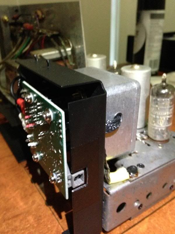
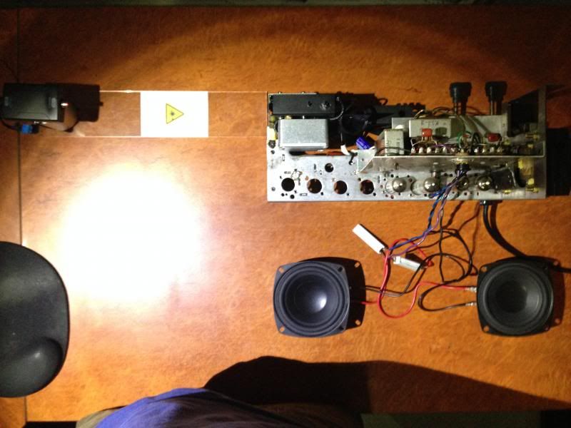
I did an S/PDIF compatible laser connection a while back, |
|
|
Return to top of page · Post #: 5 · Written at 9:21:18 AM on 24 November 2013.
|
|
|
|
Location: Canberra, ACT
Member since 23 August 2012 Member #: 1208 Postcount: 587 |
|
If you chose to use an infra-red IRDA connection rather than laser, you could give yourself much more flexibility for remote control interface and signal interruption (and more options for coffee cup placement!). You'd still have ample audio bandwidth for the capabilities of the amplifier. S/PDIF is fixed network, IRDA is untethered but line-of-sight. |
|
|
Return to top of page · Post #: 6 · Written at 11:39:50 AM on 24 November 2013.
|
|
|
|
Location: Somewhere, USA
Member since 22 October 2013 Member #: 1437 Postcount: 896 |
|
That is an idea! It was really just some fooling around back when I modified the S.PDIF converter. |
|
|
Return to top of page · Post #: 7 · Written at 12:11:33 PM on 24 November 2013.
|
|

|
Location: Melbourne, VIC
Member since 20 September 2011 Member #: 1009 Postcount: 1263 |
|
What is wrong with the 6M5 pair? |
|
|
Return to top of page · Post #: 8 · Written at 6:21:52 PM on 24 November 2013.
|
|
|
|
Location: Somewhere, USA
Member since 22 October 2013 Member #: 1437 Postcount: 896 |
|
There's nothing wrong with them, they're awesome, but I would like at least one spare set so as not to be left cold, considering the first couple of months use of the thing could be considered abusive. |
|
|
Return to top of page · Post #: 9 · Written at 10:10:25 PM on 26 November 2013.
|
|
|
|
Location: Somewhere, USA
Member since 22 October 2013 Member #: 1437 Postcount: 896 |
|
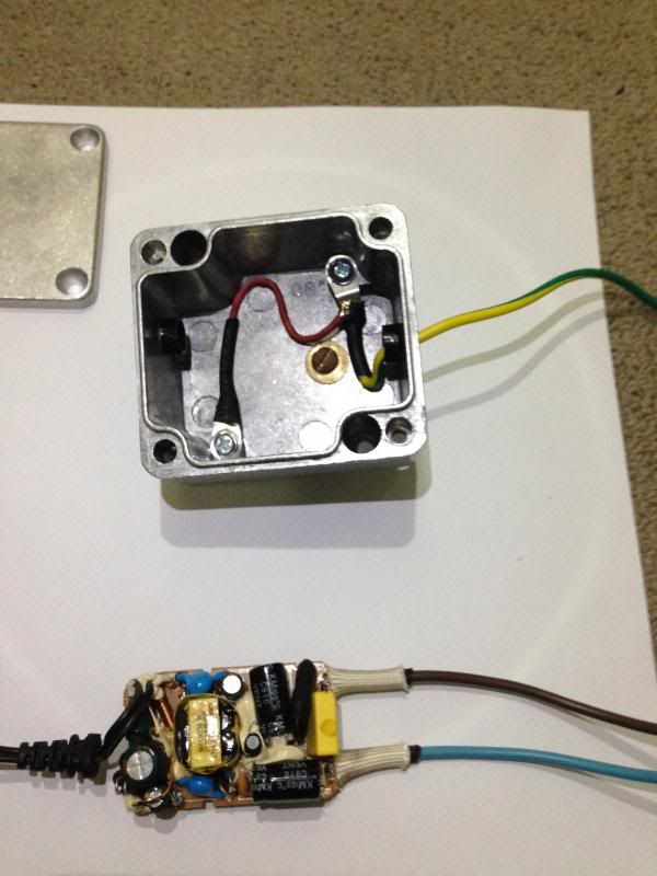
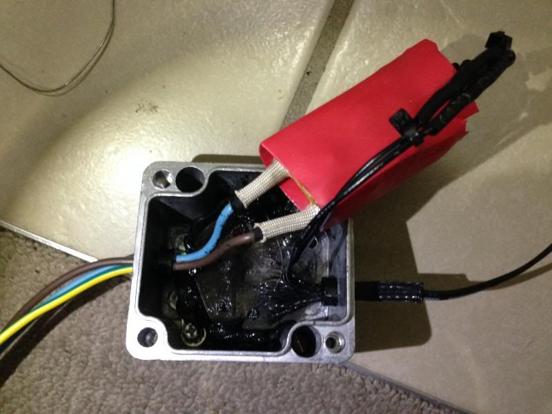
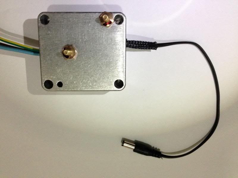
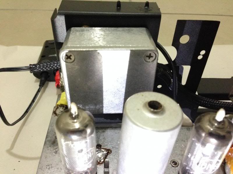
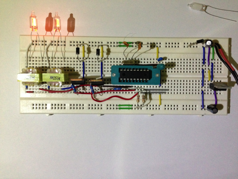
So we'll see if this PWM neon driver makes any interference! |
|
|
Return to top of page · Post #: 10 · Written at 12:49:20 PM on 30 November 2013.
|
|
|
|
Location: Somewhere, USA
Member since 22 October 2013 Member #: 1437 Postcount: 896 |
|
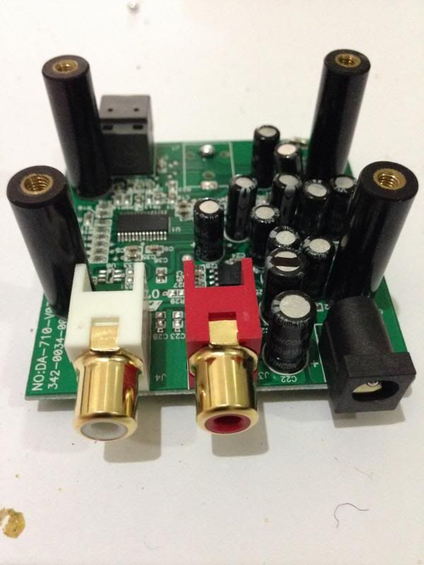
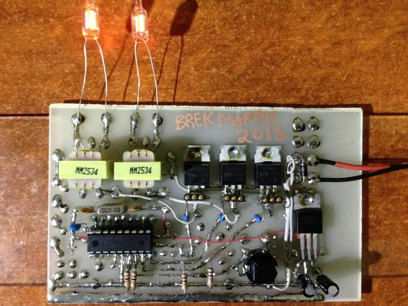
My first custom PCB.. which is two channel neon driver, |
|
|
Return to top of page · Post #: 11 · Written at 6:45:30 PM on 3 February 2014.
|
|
|
|
Location: Brisbane, QLD
Member since 24 October 2013 Member #: 1439 Postcount: 150 |
|
Nice work. I did one of those custom pcb's back in systems tech while at secondary school! Think it involved tracing out the circuit and then dipping in some chemical solution? |
|
|
Return to top of page · Post #: 12 · Written at 7:48:03 PM on 3 February 2014.
|
|

|
Administrator
Location: Naremburn, NSW
Member since 15 November 2005 Member #: 1 Postcount: 7633 |
|
Riston was the trade name for the developer used when making negatives which were then in turn used to 'print' a circuit board that was coated with the red resist film and then once exposure of the board was complete it would be dunked in developer to remove the excess resist, then dunked in ferric chloride for a few minutes to burn away the unwanted copper, hopefully leaving the tracks in place to then be drilled and soldered to. ‾‾‾‾‾‾‾‾‾‾‾‾‾‾‾‾‾‾‾‾‾‾‾‾‾‾‾‾‾‾‾‾‾‾‾‾‾‾‾‾‾‾‾‾‾‾‾‾‾‾‾‾‾‾‾‾‾‾‾‾‾‾‾‾‾‾‾‾ A valve a day keeps the transistor away... |
|
|
Return to top of page · Post #: 13 · Written at 10:40:14 AM on 4 February 2014.
|
|
|
|
Location: Somewhere, USA
Member since 22 October 2013 Member #: 1437 Postcount: 896 |
|
Sorry I don't know when you guys posted, but I missed it. |
|
|
Return to top of page · Post #: 14 · Written at 2:16:15 PM on 4 February 2014.
|
|
|
|
Administrator
Location: Naremburn, NSW
Member since 15 November 2005 Member #: 1 Postcount: 7633 |
|
Resist pens and stick on dots and tracks are a slow but equally sure way of going about it. You have to make sure the ink from the pen is applied so the copper cannot be seen through it or the ferric chloride will go through. Even if it was to just thin out the track slightly it could cause problems if the current flow is too high for it to handle. ‾‾‾‾‾‾‾‾‾‾‾‾‾‾‾‾‾‾‾‾‾‾‾‾‾‾‾‾‾‾‾‾‾‾‾‾‾‾‾‾‾‾‾‾‾‾‾‾‾‾‾‾‾‾‾‾‾‾‾‾‾‾‾‾‾‾‾‾ A valve a day keeps the transistor away... |
|
|
Return to top of page · Post #: 15 · Written at 4:02:59 PM on 4 February 2014.
|
|
|
|
Location: Somewhere, USA
Member since 22 October 2013 Member #: 1437 Postcount: 896 |
|
Well the problem is that was my only bottle of ferric chloride, |
|
|
You need to be a member to post comments on this forum.
|
|

Sign In
Vintage Radio and Television is proudly brought to you by an era where things were built with pride and made to last.
DISCLAIMER: Valve radios and televisions contain voltages that can deliver lethal shocks. You should not attempt to work on a valve radio or other electrical appliances unless you know exactly what you are doing and have gained some experience with electronics and working around high voltages. The owner, administrators and staff of Vintage Radio & Television will accept no liability for any damage, injury or loss of life that comes as a result of your use or mis-use of information on this website. Please read our Safety Warning before using this website.
WARNING: Under no circumstances should you ever apply power to a vintage radio, television or other electrical appliance you have acquired without first having it checked and serviced by an experienced person. Also, at no time should any appliance be connected to an electricity supply if the power cord is damaged. If in doubt, do not apply power.
Shintara - Keepin' It Real · VileSilencer - Maintain The Rage