
Wanted and For Sale
Forum home - Go back to Wanted and for sale
|
HMV 61-51
|
|
|
« Back ·
1 ·
Next »
|
|
|
Return to top of page · Post #: 1 · Written at 9:02:20 AM on 2 June 2013.
|
|
|
|
Location: Blue Mountains, NSW
Member since 10 March 2013 Member #: 1312 Postcount: 401 |
|
HMV's not my usual brand of radio, I stick to AWA's but I've been given a couple of reasonably complete HMV's, a 61-51 and what I think is a B13C that I'm going to restore for my daughter who loves all things retro. |
|
|
Return to top of page · Post #: 2 · Written at 10:07:37 AM on 2 June 2013.
|
|

|
Location: Wangaratta, VIC
Member since 21 February 2009 Member #: 438 Postcount: 5724 |
|
There is an easier way with the outputs of B13C. |
|
|
Return to top of page · Post #: 3 · Written at 11:21:25 AM on 2 June 2013.
|
|
|
|
Location: Blue Mountains, NSW
Member since 10 March 2013 Member #: 1312 Postcount: 401 |
|
Thanks Marc, it's all 7 pin so 6AQ5 it is! |
|
|
Return to top of page · Post #: 4 · Written at 12:40:59 PM on 2 June 2013.
|
|

|
Location: Melbourne, VIC
Member since 20 September 2011 Member #: 1009 Postcount: 1263 |
|
I just found this guide for substituting hard to get 6M5's with 6BQ5/EL84's. The good news about the 6BQ5/EL84 is that it is in current production. 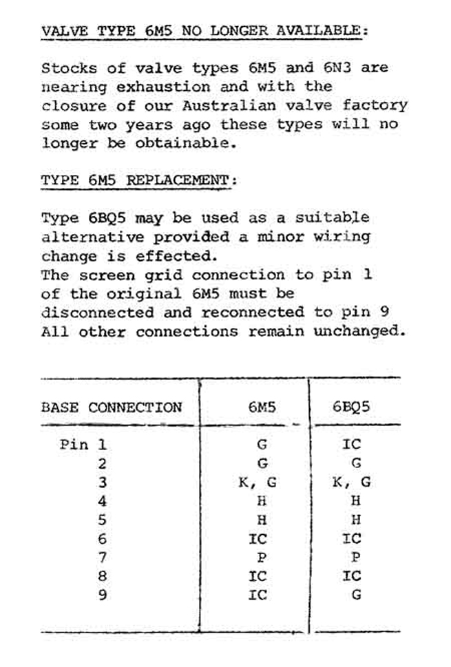 |
|
|
Return to top of page · Post #: 5 · Written at 12:59:17 PM on 2 June 2013.
|
|
|
|
Location: Wangaratta, VIC
Member since 21 February 2009 Member #: 438 Postcount: 5724 |
|
Do fit earthed cables to those. The circuit shows shielded transformers and those bleed a charge to chassis, which is best removed. |
|
|
Return to top of page · Post #: 6 · Written at 2:13:03 PM on 4 June 2013.
|
|
|
|
Location: Blue Mountains, NSW
Member since 10 March 2013 Member #: 1312 Postcount: 401 |
|
Thanks to Graham who sent me the circuit for the 61-51 but I'm still hoping for one for the 6AQ5 B13C... |
|
|
Return to top of page · Post #: 7 · Written at 3:21:10 PM on 4 June 2013.
|
|
|
|
Location: Melbourne, VIC
Member since 20 September 2011 Member #: 1009 Postcount: 1263 |
|
Warren, |
|
|
Return to top of page · Post #: 8 · Written at 4:31:07 PM on 4 June 2013.
|
|
|
|
Location: Blue Mountains, NSW
Member since 10 March 2013 Member #: 1312 Postcount: 401 |
|
Thank you for the information Monochrome625! |
|
|
Return to top of page · Post #: 9 · Written at 5:32:30 PM on 4 June 2013.
|
|
|
|
Location: Melbourne, VIC
Member since 20 September 2011 Member #: 1009 Postcount: 1263 |
|
The HMV B13C circuit is from the AORSM (Australian Official Radio Service Manual) volume 11, 1953 for 1952 radios. Unfortunately I don't have the HMV published service manual for this set as there would likely be a few more pages in it than the AORSM version. |
|
|
Return to top of page · Post #: 10 · Written at 6:10:58 PM on 4 June 2013.
|
|
|
|
Location: Blue Mountains, NSW
Member since 10 March 2013 Member #: 1312 Postcount: 401 |
|
I've heard the AORSM's mentioned a few times now. I saw an add somewhere for a full set of PDF's on CD for about $100, which I thought was a lot of money. I understand that original volumes go for big $'s so maybe $100 not so bad after all. I'll have to convince the treasurer that they are an essential tool (and useful in the kitchen too!) |
|
|
Return to top of page · Post #: 11 · Written at 7:33:53 PM on 4 June 2013.
|
|
|
|
Location: Melbourne, VIC
Member since 20 September 2011 Member #: 1009 Postcount: 1263 |
|
$100 is not bad considering the time and effort going in to scanning 14 volumes at an average of 400 pages each. Most of my AORSM books ( I'm missing volumes 3, 4, 9 & 14) are all falling apart. I get the impression these books were not that well made to begin with. Makes it easier to scan though. |
|
|
Return to top of page · Post #: 12 · Written at 8:20:46 PM on 4 June 2013.
|
|
|
|
Location: Wangaratta, VIC
Member since 21 February 2009 Member #: 438 Postcount: 5724 |
|
Earthed cable applies to both. If you look at the transformer drawing on the circuit diagram you will note the earth symbol eminating from the core. |
|
|
« Back ·
1 ·
Next »
|
|
|
You need to be a member to post comments on this forum.
|
|
Sign In
Vintage Radio and Television is proudly brought to you by an era where things were built with pride and made to last.
DISCLAIMER: Valve radios and televisions contain voltages that can deliver lethal shocks. You should not attempt to work on a valve radio or other electrical appliances unless you know exactly what you are doing and have gained some experience with electronics and working around high voltages. The owner, administrators and staff of Vintage Radio & Television will accept no liability for any damage, injury or loss of life that comes as a result of your use or mis-use of information on this website. Please read our Safety Warning before using this website.
WARNING: Under no circumstances should you ever apply power to a vintage radio, television or other electrical appliance you have acquired without first having it checked and serviced by an experienced person. Also, at no time should any appliance be connected to an electricity supply if the power cord is damaged. If in doubt, do not apply power.
Shintara - Keepin' It Real · VileSilencer - Maintain The Rage