
General Discussion
Forum home - Go back to General discussion
|
'31 Airzone Console
|
|
|
Return to top of page · Post #: 61 · Written at 8:44:22 PM on 23 December 2013.
|
|
|
|
Location: Somewhere, USA
Member since 22 October 2013 Member #: 1437 Postcount: 896 |
|
Got it back today |
|
|
Return to top of page · Post #: 62 · Written at 9:45:47 PM on 23 December 2013.
|
|

|
Administrator
Location: Naremburn, NSW
Member since 15 November 2005 Member #: 1 Postcount: 7311 |
|
The low volume could be due to a number of things. ‾‾‾‾‾‾‾‾‾‾‾‾‾‾‾‾‾‾‾‾‾‾‾‾‾‾‾‾‾‾‾‾‾‾‾‾‾‾‾‾‾‾‾‾‾‾‾‾‾‾‾‾‾‾‾‾‾‾‾‾‾‾‾‾‾‾‾‾ A valve a day keeps the transistor away... |
|
|
Return to top of page · Post #: 63 · Written at 9:52:26 PM on 23 December 2013.
|
|
|
|
Location: Somewhere, USA
Member since 22 October 2013 Member #: 1437 Postcount: 896 |
|
Problem with all of those points is the phono input is fine |
|
|
Return to top of page · Post #: 64 · Written at 9:53:35 PM on 23 December 2013.
|
|
|
|
Administrator
Location: Naremburn, NSW
Member since 15 November 2005 Member #: 1 Postcount: 7311 |
|
So the sound is okay except for the radio? Add a longer/higher antenna and see what happens. ‾‾‾‾‾‾‾‾‾‾‾‾‾‾‾‾‾‾‾‾‾‾‾‾‾‾‾‾‾‾‾‾‾‾‾‾‾‾‾‾‾‾‾‾‾‾‾‾‾‾‾‾‾‾‾‾‾‾‾‾‾‾‾‾‾‾‾‾ A valve a day keeps the transistor away... |
|
|
Return to top of page · Post #: 65 · Written at 9:56:25 PM on 23 December 2013.
|
|
|
|
Location: Somewhere, USA
Member since 22 October 2013 Member #: 1437 Postcount: 896 |
|
Yes, I was feeding another radio into the phono before the radio section worked, |
|
|
Return to top of page · Post #: 66 · Written at 9:59:38 PM on 23 December 2013.
|
|
|
|
Administrator
Location: Naremburn, NSW
Member since 15 November 2005 Member #: 1 Postcount: 7311 |
|
If audio via the radio is still low it may also require realignment. Turning the screws on the coils the wrong way will lower volume in about half a turn so care will be required. ‾‾‾‾‾‾‾‾‾‾‾‾‾‾‾‾‾‾‾‾‾‾‾‾‾‾‾‾‾‾‾‾‾‾‾‾‾‾‾‾‾‾‾‾‾‾‾‾‾‾‾‾‾‾‾‾‾‾‾‾‾‾‾‾‾‾‾‾ A valve a day keeps the transistor away... |
|
|
Return to top of page · Post #: 67 · Written at 10:08:23 PM on 23 December 2013.
|
|
|
|
Location: Somewhere, USA
Member since 22 October 2013 Member #: 1437 Postcount: 896 |
|
Ok, .. I will have more questions later, just to gain understanding, even if not required to fix the thing. |
|
|
Return to top of page · Post #: 68 · Written at 10:32:28 PM on 23 December 2013.
|
|
|
|
Administrator
Location: Naremburn, NSW
Member since 15 November 2005 Member #: 1 Postcount: 7311 |
|
A lot of radios had stepped switches instead of a variable tone control and such beasts usually had three settings though a few higher prices models had four or five. ‾‾‾‾‾‾‾‾‾‾‾‾‾‾‾‾‾‾‾‾‾‾‾‾‾‾‾‾‾‾‾‾‾‾‾‾‾‾‾‾‾‾‾‾‾‾‾‾‾‾‾‾‾‾‾‾‾‾‾‾‾‾‾‾‾‾‾‾ A valve a day keeps the transistor away... |
|
|
Return to top of page · Post #: 69 · Written at 10:40:16 PM on 23 December 2013.
|
|

|
Location: Melbourne, VIC
Member since 20 September 2011 Member #: 1009 Postcount: 1182 |
|
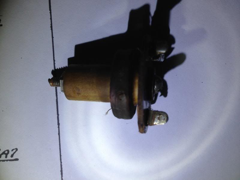
In this case the tone control (C12) appears to be some kind of variable condenser. Never seen anything quite like it. Got me stumped too! |
|
|
Return to top of page · Post #: 70 · Written at 10:55:31 PM on 23 December 2013.
|
|
|
|
Location: Canberra, ACT
Member since 23 August 2012 Member #: 1208 Postcount: 584 |
|
If the tone control is a rotary switch (you mention more and more lugs) then it will be working by switching in/out more tiny capacitors (say 10-30pf) in increments to alter the modulation in the audio. |
|
|
Return to top of page · Post #: 71 · Written at 12:02:05 AM on 24 December 2013.
|
|
|
|
Location: Somewhere, USA
Member since 22 October 2013 Member #: 1437 Postcount: 896 |
|
There are no capacitors though, and only two terminals to the whole thing. They can't make capacitors that small, they would have to be as small as our ceramic disc today. |
|
|
Return to top of page · Post #: 72 · Written at 9:16:57 AM on 24 December 2013.
|
|
|
|
Location: Canberra, ACT
Member since 23 August 2012 Member #: 1208 Postcount: 584 |
|
.. then it must be generating variable capacitance within the switching device, or varying the mix with some external capacitor. Internal variance can be done by a lug on the rotor "hovering" over each lug on the stator, creating a simple air capacitance between the two points based on the distance between the two points. No discrete capacitors would be visible. Interested to see pictures. |
|
|
Return to top of page · Post #: 73 · Written at 11:45:03 AM on 24 December 2013.
|
|
|
|
Location: Somewhere, USA
Member since 22 October 2013 Member #: 1437 Postcount: 896 |
|
We are about to be overrun with kids, so I packed it all up! |
|
|
Return to top of page · Post #: 74 · Written at 7:02:56 PM on 24 December 2013.
|
|
|
|
Location: NSW
Member since 10 June 2010 Member #: 681 Postcount: 1261 |
|
I wonder if a coil that isn't shown in the schematic may be a filter for a very strong local station, especially if the coil is in the RF circuit. Something that might have been added by a local serviceman. |
|
|
Return to top of page · Post #: 75 · Written at 10:00:35 PM on 24 December 2013.
|
|
|
|
Location: Somewhere, USA
Member since 22 October 2013 Member #: 1437 Postcount: 896 |
|
It is in the schematic to the right of the leftmost 6D7. |
|
|
You need to be a member to post comments on this forum.
|
|


Sign In
Vintage Radio and Television is proudly brought to you by an era where things were built with pride and made to last.
DISCLAIMER: Valve radios and televisions contain voltages that can deliver lethal shocks. You should not attempt to work on a valve radio or other electrical appliances unless you know exactly what you are doing and have gained some experience with electronics and working around high voltages. The owner, administrators and staff of Vintage Radio & Television will accept no liability for any damage, injury or loss of life that comes as a result of your use or mis-use of information on this website. Please read our Safety Warning before using this website.
WARNING: Under no circumstances should you ever apply power to a vintage radio, television or other electrical appliance you have acquired without first having it checked and serviced by an experienced person. Also, at no time should any appliance be connected to an electricity supply if the power cord is damaged. If in doubt, do not apply power.
Shintara - Keepin' It Real · VileSilencer - Maintain The Rage