
General Discussion
Forum home - Go back to General discussion
|
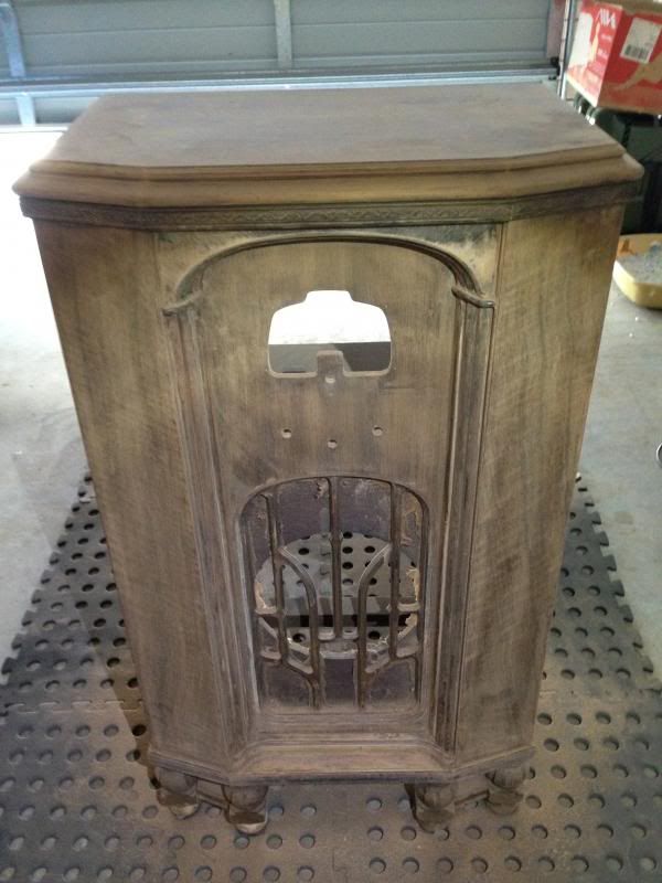
'31 Airzone Console
|
|
|
Return to top of page · Post #: 31 · Written at 9:38:39 AM on 16 December 2013.
|
|
|
|
Location: Somewhere, USA
Member since 22 October 2013 Member #: 1437 Postcount: 896 |
|
Thanks that makes much more sense |
|
|
Return to top of page · Post #: 32 · Written at 3:37:56 PM on 17 December 2013.
|
|
|
|
Location: Somewhere, USA
Member since 22 October 2013 Member #: 1437 Postcount: 896 |
|
Bummer,.. power transformer high voltage secondary shorted to the chassis, |
|
|
Return to top of page · Post #: 33 · Written at 5:55:22 PM on 17 December 2013.
|
|
|
|
Location: NSW
Member since 10 June 2010 Member #: 681 Postcount: 1261 |
|
Sometimes the winding voltages are recorded on a bakelite tag strip on the transformer- easy to miss if covered in dust and gunk. |
|
|
Return to top of page · Post #: 34 · Written at 6:59:20 PM on 17 December 2013.
|
|
|
|
Location: Somewhere, USA
Member since 22 October 2013 Member #: 1437 Postcount: 896 |
|
Thanks STC, I haven't removed it to even look yet, |
|
|
Return to top of page · Post #: 35 · Written at 10:12:07 PM on 17 December 2013.
|
|
|
|
Location: Somewhere, USA
Member since 22 October 2013 Member #: 1437 Postcount: 896 |
|
The resistance across the high voltage secondary is about 560 Ohms, |
|
|
Return to top of page · Post #: 36 · Written at 5:01:00 PM on 20 December 2013.
|
|
|
|
Location: Somewhere, USA
Member since 22 October 2013 Member #: 1437 Postcount: 896 |
|
|
|
|
Return to top of page · Post #: 37 · Written at 1:11:08 PM on 21 December 2013.
|
|
|
|
Location: Somewhere, USA
Member since 22 October 2013 Member #: 1437 Postcount: 896 |
|
|
|
|
Return to top of page · Post #: 38 · Written at 1:56:14 PM on 21 December 2013.
|
|

|
Administrator
Location: Naremburn, NSW
Member since 15 November 2005 Member #: 1 Postcount: 7311 |
|
795 might seem high though it is quite true that the no-load voltage is higher. From here I would suggest running the chassis for about ten minutes, monitoring the voltage. if it remains stable (and if the transformer is not getting warm) it should be safe to start adding valves. I usually add one at a time, starting with the rectifier and working through to the power amplifier. ‾‾‾‾‾‾‾‾‾‾‾‾‾‾‾‾‾‾‾‾‾‾‾‾‾‾‾‾‾‾‾‾‾‾‾‾‾‾‾‾‾‾‾‾‾‾‾‾‾‾‾‾‾‾‾‾‾‾‾‾‾‾‾‾‾‾‾‾ A valve a day keeps the transistor away... |
|
|
Return to top of page · Post #: 39 · Written at 2:27:25 PM on 21 December 2013.
|
|
|
|
Location: Somewhere, USA
Member since 22 October 2013 Member #: 1437 Postcount: 896 |
|
It wouldn't be game over, but despite my work underneath, |
|
|
Return to top of page · Post #: 40 · Written at 4:27:38 PM on 21 December 2013.
|
|
|
|
Location: Blue Mountains, NSW
Member since 10 March 2013 Member #: 1312 Postcount: 401 |
|
After putting the rectifier in and monitoring B+, which will be high because it's unloaded, I turn it off again watching the B+. If the electros have formed up ok and there's no bleed resistors the B+ should drop slowly. If all seems well I'll leave it powered up for 20 minutes or so then turn it off and check for any warm components. The only things that should be hot are the rectifier itself and possibly the choke. A few resistors will be warm and the transformer shouldn't be more than slightly warm. No capacitors should be even the slightest bit warm. Then as Brad suggests add the valves one at a time watching the voltages. Some lucky people have a variac but I made up a dim bulb tester I use during this procedure although it has caught me out a few times chasing low voltages when I've forgotten I was using it! |
|
|
Return to top of page · Post #: 41 · Written at 4:43:37 PM on 21 December 2013.
|
|
|
|
Location: Somewhere, USA
Member since 22 October 2013 Member #: 1437 Postcount: 896 |
|
|
|
|
Return to top of page · Post #: 42 · Written at 4:49:16 PM on 21 December 2013.
|
|

|
Location: Wangaratta, VIC
Member since 21 February 2009 Member #: 438 Postcount: 5267 |
|
I am having difficulties with the transformer, incoming in late on this. |
|
|
Return to top of page · Post #: 43 · Written at 4:56:07 PM on 21 December 2013.
|
|
|
|
Location: Somewhere, USA
Member since 22 October 2013 Member #: 1437 Postcount: 896 |
|
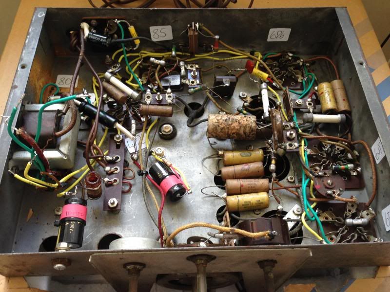
You're not looking at the latest under chassis picture ;) |
|
|
Return to top of page · Post #: 44 · Written at 5:39:06 PM on 21 December 2013.
|
|
|
|
Location: Somewhere, USA
Member since 22 October 2013 Member #: 1437 Postcount: 896 |
|
I was testing right across the secondary for that reading, |
|
|
Return to top of page · Post #: 45 · Written at 5:40:59 PM on 21 December 2013.
|
|
|
|
Location: Somewhere, USA
Member since 22 October 2013 Member #: 1437 Postcount: 896 |
|
|
|
|
You need to be a member to post comments on this forum.
|
|

Sign In
Vintage Radio and Television is proudly brought to you by an era where things were built with pride and made to last.
DISCLAIMER: Valve radios and televisions contain voltages that can deliver lethal shocks. You should not attempt to work on a valve radio or other electrical appliances unless you know exactly what you are doing and have gained some experience with electronics and working around high voltages. The owner, administrators and staff of Vintage Radio & Television will accept no liability for any damage, injury or loss of life that comes as a result of your use or mis-use of information on this website. Please read our Safety Warning before using this website.
WARNING: Under no circumstances should you ever apply power to a vintage radio, television or other electrical appliance you have acquired without first having it checked and serviced by an experienced person. Also, at no time should any appliance be connected to an electricity supply if the power cord is damaged. If in doubt, do not apply power.
Shintara - Keepin' It Real · VileSilencer - Maintain The Rage