
General Discussion
Forum home - Go back to General discussion
|
Chieftain by Motor Spares Ltd., Melbourne
|
|
|
Return to top of page · Post #: 31 · Written at 2:02:37 PM on 7 July 2017.
|
|

|
Location: Latham, ACT
Member since 21 February 2015 Member #: 1705 Postcount: 2158 |
|
Guys that is fantastic advice . Now I know where I am at . Thank you so much Marcc, Ian and Fred now its all clear. |
|
|
Return to top of page · Post #: 32 · Written at 10:41:44 PM on 7 July 2017.
|
|
|
|
Location: Latham, ACT
Member since 21 February 2015 Member #: 1705 Postcount: 2158 |
|
Guys the radio had no battery plugs on the leads at all. That's why I am being very cautious as you never know who has done what |
|
|
Return to top of page · Post #: 33 · Written at 11:08:11 PM on 7 July 2017.
|
|
|
|
Location: Belrose, NSW
Member since 31 December 2015 Member #: 1844 Postcount: 2373 |
|
You might be ready to test the filament (1.5v) circuit. |
|
|
Return to top of page · Post #: 34 · Written at 12:19:28 PM on 8 July 2017.
|
|
|
|
Location: Latham, ACT
Member since 21 February 2015 Member #: 1705 Postcount: 2158 |
|
Well I have sound but no stations. I havent tested the valves though and I know the switch is a bit dicky. as it doesnt switch on unless I fiddle with it. 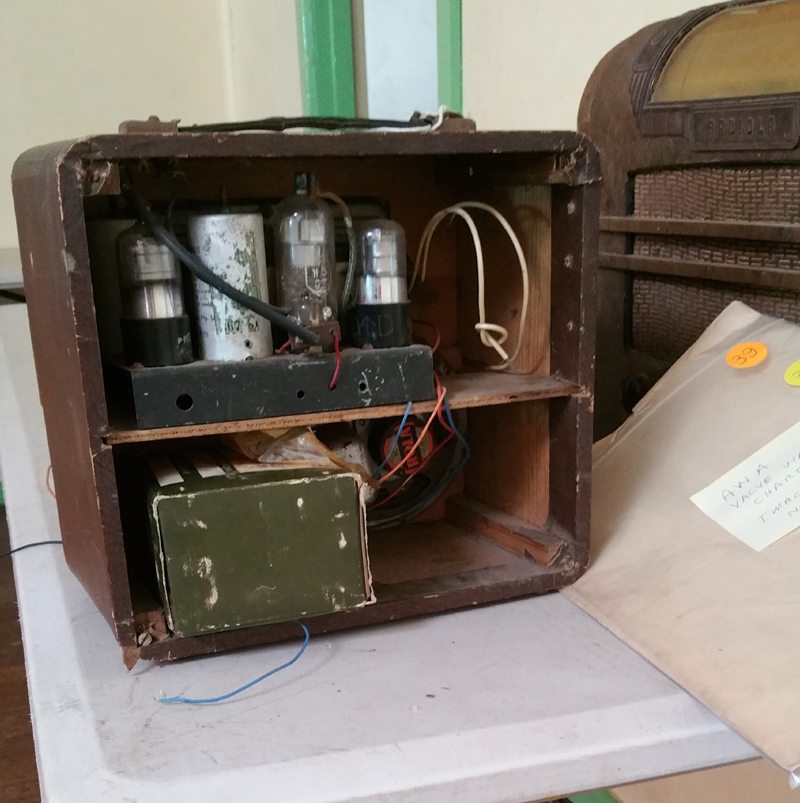 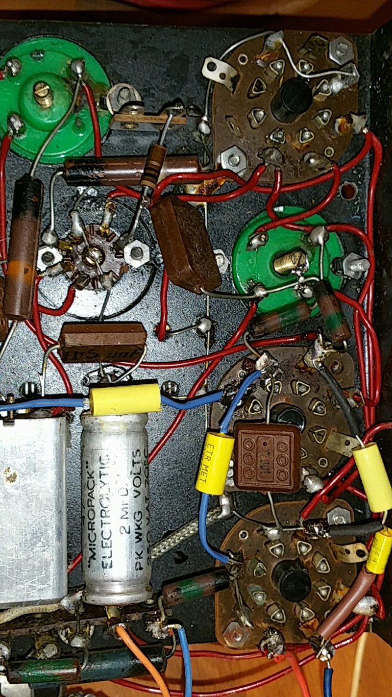 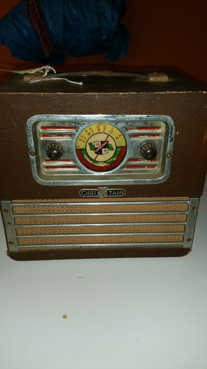 |
|
|
Return to top of page · Post #: 35 · Written at 12:40:43 PM on 8 July 2017.
|
|
|
|
Location: Belrose, NSW
Member since 31 December 2015 Member #: 1844 Postcount: 2373 |
|
Switch contact issues are just about universal in battery valve radios. You need very low contact resistance, especially in the A (1.5v) circuit where you can tolerate no voltage drop at all. With silver plated contacts that just won't happen after 70 years! |
|
|
Return to top of page · Post #: 36 · Written at 1:18:56 PM on 8 July 2017.
|
|
|
|
Location: Latham, ACT
Member since 21 February 2015 Member #: 1705 Postcount: 2158 |
|
Ok Here is the issue. All valves tested faulty ie blown filaments. I was able to get some very low level and garbled signal. I know this sounds strange . Its probably some form of inductance. iI have tested the speaker transformer and its all ok. I am pretty happy with myself as I know that this will work. Obviously my fears were justified in thinking some one has tampered with this. Earlier I thought I could see the filaments had detached but my eyesight isnt as it was. Ian if you have all these valves then I would love to have them. and I will be able to fix you up for them shortly. |
|
|
Return to top of page · Post #: 37 · Written at 1:36:36 PM on 8 July 2017.
|
|
|
|
Location: Latham, ACT
Member since 21 February 2015 Member #: 1705 Postcount: 2158 |
|
What I mean by garbled signal is I actually got the ABC. |
|
|
Return to top of page · Post #: 38 · Written at 1:39:02 PM on 8 July 2017.
|
|
|
|
Location: Latham, ACT
Member since 21 February 2015 Member #: 1705 Postcount: 2158 |
|
I did actually test the filament circuit as you said Ian and I got 5 ohms for the lot. |
|
|
Return to top of page · Post #: 39 · Written at 1:59:45 PM on 8 July 2017.
|
|
|
|
Location: Belrose, NSW
Member since 31 December 2015 Member #: 1844 Postcount: 2373 |
|
Well, it looks like you won't be needing those valves! |
|
|
Return to top of page · Post #: 40 · Written at 2:27:32 PM on 8 July 2017.
|
|
|
|
Location: Latham, ACT
Member since 21 February 2015 Member #: 1705 Postcount: 2158 |
|
I have tested the filament pins and they are all open circuit. That's the confusing thing. Very very low signal. |
|
|
Return to top of page · Post #: 41 · Written at 2:32:20 PM on 8 July 2017.
|
|
|
|
Location: Latham, ACT
Member since 21 February 2015 Member #: 1705 Postcount: 2158 |
|
So I definitely do need the valves. I consulted my Philips valve data book and made sure I was testing the correct pins and they all tested as open circuit. I even tested a valve that I know to be good with the multimeter and it tested ok. So my testing methods do work |
|
|
Return to top of page · Post #: 42 · Written at 3:20:09 PM on 8 July 2017.
|
|
|
|
Location: Belrose, NSW
Member since 31 December 2015 Member #: 1844 Postcount: 2373 |
|
You must be VERY close to the Gungahlin transmitter if those filaments are O/C! |
|
|
Return to top of page · Post #: 43 · Written at 4:41:42 PM on 8 July 2017.
|
|
|
|
Location: Latham, ACT
Member since 21 February 2015 Member #: 1705 Postcount: 2158 |
|
Apparently they are ok . It has a loop antenna that's in its case . But only attached with one lead , why one lead apparently it's tuned and the radio won't work with out it. And I was counting the pins wrong. |
|
|
Return to top of page · Post #: 44 · Written at 5:07:33 PM on 8 July 2017.
|
|
|
|
Location: Belrose, NSW
Member since 31 December 2015 Member #: 1844 Postcount: 2373 |
|
Yeah, easy to do. |
|
|
Return to top of page · Post #: 45 · Written at 7:24:24 PM on 8 July 2017.
|
|

|
Location: Wangaratta, VIC
Member since 21 February 2009 Member #: 438 Postcount: 5259 |
|
Why do I see new NP caps & an old elecctrolytic in the photo? |
|
|
You need to be a member to post comments on this forum.
|
|
 . I am happy as I know everything else is good. I can actually see one of the filaments has visibly detached from it's post.
Sign In
Vintage Radio and Television is proudly brought to you by an era where things were built with pride and made to last.
DISCLAIMER: Valve radios and televisions contain voltages that can deliver lethal shocks. You should not attempt to work on a valve radio or other electrical appliances unless you know exactly what you are doing and have gained some experience with electronics and working around high voltages. The owner, administrators and staff of Vintage Radio & Television will accept no liability for any damage, injury or loss of life that comes as a result of your use or mis-use of information on this website. Please read our Safety Warning before using this website.
WARNING: Under no circumstances should you ever apply power to a vintage radio, television or other electrical appliance you have acquired without first having it checked and serviced by an experienced person. Also, at no time should any appliance be connected to an electricity supply if the power cord is damaged. If in doubt, do not apply power.
Shintara - Keepin' It Real · VileSilencer - Maintain The Rage