
General Discussion
Forum home - Go back to General discussion
|
Chieftain by Motor Spares Ltd., Melbourne
|
|
|
Return to top of page · Post #: 16 · Written at 9:29:11 PM on 3 July 2017.
|
|

|
Location: Sydney, NSW
Member since 28 January 2011 Member #: 823 Postcount: 6689 |
|
All octal except for 1R5. |
|
|
Return to top of page · Post #: 17 · Written at 10:27:55 PM on 3 July 2017.
|
|
|
|
Location: Belrose, NSW
Member since 31 December 2015 Member #: 1844 Postcount: 2373 |
|
1R5, 1N5GT, 1H5GT, 1Q5GT. |
|
|
Return to top of page · Post #: 18 · Written at 10:28:22 PM on 3 July 2017.
|
|

|
Location: Latham, ACT
Member since 21 February 2015 Member #: 1705 Postcount: 2158 |
|
1H5GT, 1R5, 1N7GT and 1Q5GT |
|
|
Return to top of page · Post #: 19 · Written at 10:59:06 PM on 3 July 2017.
|
|
|
|
Location: Belrose, NSW
Member since 31 December 2015 Member #: 1844 Postcount: 2373 |
|
No such thing as a 1N7GT..... |
|
|
Return to top of page · Post #: 20 · Written at 11:19:46 PM on 3 July 2017.
|
|
|
|
Location: Latham, ACT
Member since 21 February 2015 Member #: 1705 Postcount: 2158 |
|
Sorry I must have hit the wrong number lol. |
|
|
Return to top of page · Post #: 21 · Written at 12:05:05 AM on 4 July 2017.
|
|
|
|
Location: Sydney, NSW
Member since 28 January 2011 Member #: 823 Postcount: 6689 |
|
The 1R5 has replaced a 1A7GT at some stage with a chassis washer, looks like factory. |
|
|
Return to top of page · Post #: 22 · Written at 2:33:41 PM on 4 July 2017.
|
|
|
|
Location: Latham, ACT
Member since 21 February 2015 Member #: 1705 Postcount: 2158 |
|
I have sent photos 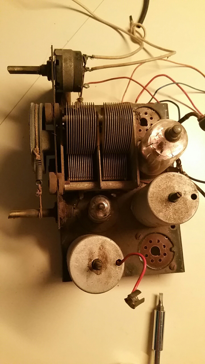  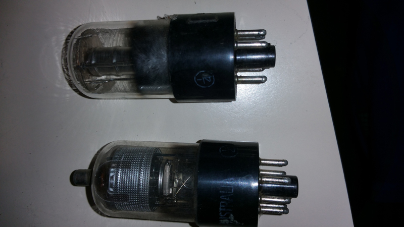 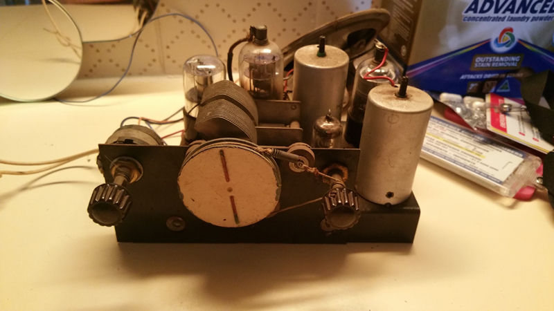 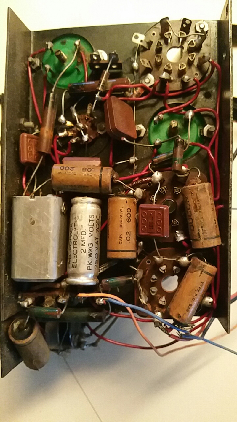 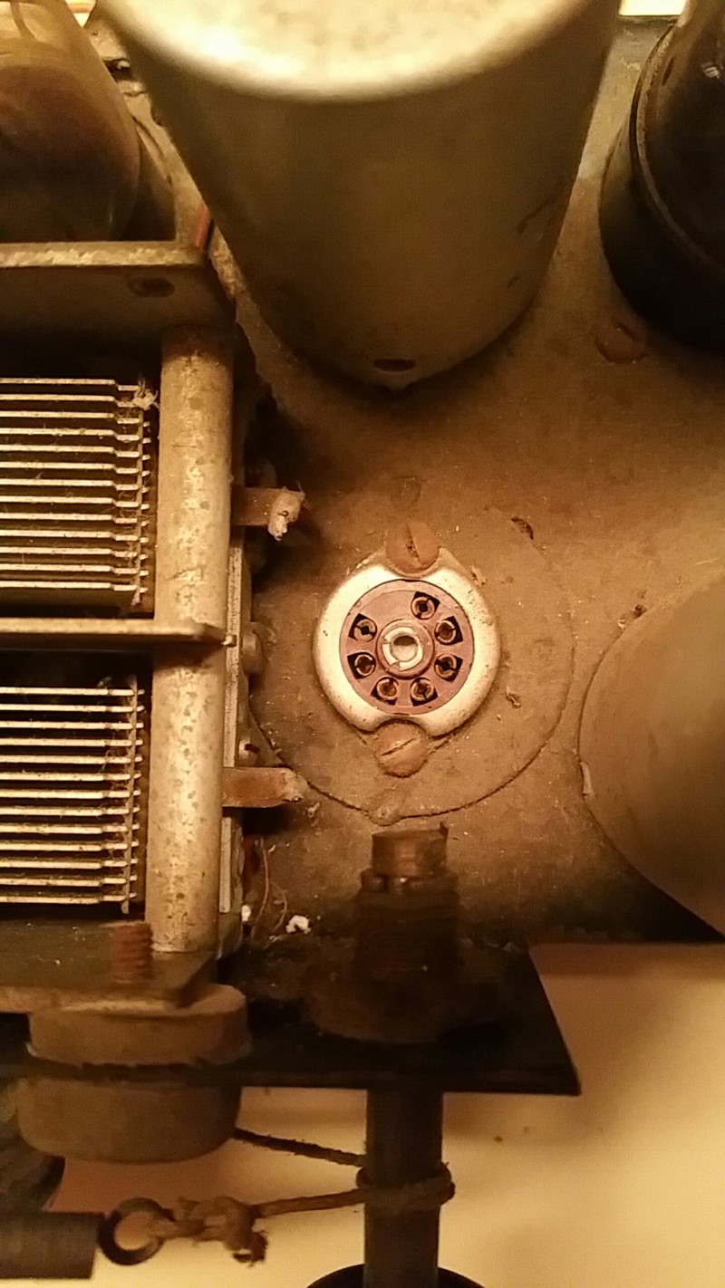 |
|
|
Return to top of page · Post #: 23 · Written at 9:07:15 PM on 6 July 2017.
|
|

|
Administrator
Location: Naremburn, NSW
Member since 15 November 2005 Member #: 1 Postcount: 7307 |
|
Photos uploaded to Post 22. ‾‾‾‾‾‾‾‾‾‾‾‾‾‾‾‾‾‾‾‾‾‾‾‾‾‾‾‾‾‾‾‾‾‾‾‾‾‾‾‾‾‾‾‾‾‾‾‾‾‾‾‾‾‾‾‾‾‾‾‾‾‾‾‾‾‾‾‾ A valve a day keeps the transistor away... |
|
|
Return to top of page · Post #: 24 · Written at 9:34:22 PM on 6 July 2017.
|
|

|
Location: Hill Top, NSW
Member since 18 September 2015 Member #: 1801 Postcount: 2017 |
|
Looks like an easy job, assuming the coils and transformer(s) are ok. |
|
|
Return to top of page · Post #: 25 · Written at 9:54:58 PM on 6 July 2017.
|
|
|
|
Location: Belrose, NSW
Member since 31 December 2015 Member #: 1844 Postcount: 2373 |
|
HMMM - the 1H5 and 1N5 I didn't actually mail today are G type, not GT. Might not fit, too tall. I'll have another rummage! |
|
|
Return to top of page · Post #: 26 · Written at 10:26:47 PM on 6 July 2017.
|
|
|
|
Location: Sydney, NSW
Member since 28 January 2011 Member #: 823 Postcount: 6689 |
|
No case? |
|
|
Return to top of page · Post #: 27 · Written at 11:51:35 PM on 6 July 2017.
|
|
|
|
Location: Latham, ACT
Member since 21 February 2015 Member #: 1705 Postcount: 2158 |
|
There is plenty of headroom Ian the case is very roomy I will send Brad a picture of the case. I thought I did. |
|
|
Return to top of page · Post #: 28 · Written at 12:57:03 AM on 7 July 2017.
|
|

|
Location: Wangaratta, VIC
Member since 21 February 2009 Member #: 438 Postcount: 5259 |
|
Seriously wrong assumptions. |
|
|
Return to top of page · Post #: 29 · Written at 12:21:37 PM on 7 July 2017.
|
|
|
|
Location: Belrose, NSW
Member since 31 December 2015 Member #: 1844 Postcount: 2373 |
|
Hi Carl |
|
|
Return to top of page · Post #: 30 · Written at 1:00:05 PM on 7 July 2017.
|
|
|
|
Location: Toongabbie, NSW
Member since 19 November 2015 Member #: 1828 Postcount: 1251 |
|
Good photos Carl. |
|
|
You need to be a member to post comments on this forum.
|
|
Sign In
Vintage Radio and Television is proudly brought to you by an era where things were built with pride and made to last.
DISCLAIMER: Valve radios and televisions contain voltages that can deliver lethal shocks. You should not attempt to work on a valve radio or other electrical appliances unless you know exactly what you are doing and have gained some experience with electronics and working around high voltages. The owner, administrators and staff of Vintage Radio & Television will accept no liability for any damage, injury or loss of life that comes as a result of your use or mis-use of information on this website. Please read our Safety Warning before using this website.
WARNING: Under no circumstances should you ever apply power to a vintage radio, television or other electrical appliance you have acquired without first having it checked and serviced by an experienced person. Also, at no time should any appliance be connected to an electricity supply if the power cord is damaged. If in doubt, do not apply power.
Shintara - Keepin' It Real · VileSilencer - Maintain The Rage