
Vintage Television
Forum home - Go back to Vintage Television
|
Kriesler Styleline 24 solid state TV Service Manual wanted
|
|
|
Return to top of page · Post #: 1 · Written at 12:26:40 PM on 6 April 2019.
|
|
|
|
Location: Melbourne, VIC
Member since 6 April 2019 Member #: 2344 Postcount: 12 |
|
A friend of a friend of a ... has one of these in their backroom. Hasn't been used since early 80's but has been kept inside. |
|
|
Return to top of page · Post #: 2 · Written at 1:22:00 PM on 6 April 2019.
|
|

|
Location: Melbourne, VIC
Member since 20 September 2011 Member #: 1009 Postcount: 1267 |
|
I think the Styleline 24 is a 1972 Model E234. Unfortunately I don't know what chassis series is used in this model. |
|
|
Return to top of page · Post #: 3 · Written at 3:09:08 PM on 6 April 2019.
|
|
|
|
Location: Melbourne, VIC
Member since 6 April 2019 Member #: 2344 Postcount: 12 |
|
Thank you very much. |
|
|
Return to top of page · Post #: 4 · Written at 5:03:53 PM on 7 April 2019.
|
|
|
|
Location: Melbourne, VIC
Member since 6 April 2019 Member #: 2344 Postcount: 12 |
|
I have the TV in hand now. Its chassis is 49-7. |
|
|
Return to top of page · Post #: 5 · Written at 5:25:37 AM on 8 April 2019.
|
|
|
|
Location: Melbourne, VIC
Member since 20 September 2011 Member #: 1009 Postcount: 1267 |
|
Yes I have the full manual for the 49-7 chassis series. |
|
|
Return to top of page · Post #: 6 · Written at 6:03:18 PM on 8 April 2019.
|
|
|
|
Location: Melbourne, VIC
Member since 6 April 2019 Member #: 2344 Postcount: 12 |
|
No hurry at all. I'm very grateful for your help. |
|
|
Return to top of page · Post #: 7 · Written at 2:07:20 PM on 15 April 2019.
|
|
|
|
Location: Belrose, NSW
Member since 31 December 2015 Member #: 1844 Postcount: 2714 |
|
I know the 49-7 chassis well, used to fix many of them under warranty when they were new. |
|
|
Return to top of page · Post #: 8 · Written at 7:27:11 PM on 15 April 2019.
|
|
|
|
Location: Melbourne, VIC
Member since 6 April 2019 Member #: 2344 Postcount: 12 |
|
Yes, the green board. That cap is in the EHT section. That is also where the hole in the board is. |
|
|
Return to top of page · Post #: 9 · Written at 6:56:57 AM on 16 April 2019.
|
|
|
|
Location: Melbourne, VIC
Member since 20 September 2011 Member #: 1009 Postcount: 1267 |
|
Sorry for the delay. |
|
|
Return to top of page · Post #: 10 · Written at 1:10:33 PM on 16 April 2019.
|
|
|
|
Location: Belrose, NSW
Member since 31 December 2015 Member #: 1844 Postcount: 2714 |
|
A pic on the hole in the board might help, or if you could tell me which resistor or other component burned the board by reference to the component layout in the manual when you get it. |
|
|
Return to top of page · Post #: 11 · Written at 6:53:45 PM on 16 April 2019.
|
|

|
Administrator
Location: Naremburn, NSW
Member since 15 November 2005 Member #: 1 Postcount: 7643 |
|
Documents uploaded to Posts 5 and 9 (identical). ‾‾‾‾‾‾‾‾‾‾‾‾‾‾‾‾‾‾‾‾‾‾‾‾‾‾‾‾‾‾‾‾‾‾‾‾‾‾‾‾‾‾‾‾‾‾‾‾‾‾‾‾‾‾‾‾‾‾‾‾‾‾‾‾‾‾‾‾ A valve a day keeps the transistor away... |
|
|
Return to top of page · Post #: 12 · Written at 8:25:06 PM on 17 April 2019.
|
|
|
|
Location: Melbourne, VIC
Member since 6 April 2019 Member #: 2344 Postcount: 12 |
|
Thank you so much. I downloaded the documents a little earlier and I must admit parts of the schematic have me a bit baffled. The service manual will be a great help in understanding the circuit. Again, thank you. |
|
|
Return to top of page · Post #: 13 · Written at 3:51:22 PM on 18 April 2019.
|
|
|
|
Location: Belrose, NSW
Member since 31 December 2015 Member #: 1844 Postcount: 2714 |
|
From what you tell me it'd be safe to power up as is. No need to disconnect the CRT. |
|
|
Return to top of page · Post #: 14 · Written at 8:25:04 PM on 18 April 2019.
|
|
|
|
Location: Melbourne, VIC
Member since 6 April 2019 Member #: 2344 Postcount: 12 |
|
Thanks for your tips. 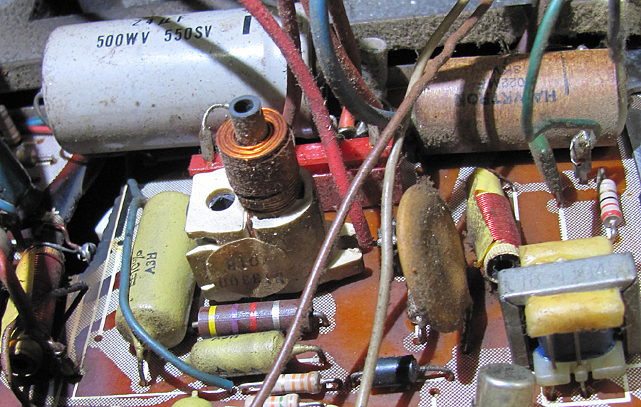 |
|
|
Return to top of page · Post #: 15 · Written at 4:29:18 PM on 20 April 2019.
|
|
|
|
Administrator
Location: Naremburn, NSW
Member since 15 November 2005 Member #: 1 Postcount: 7643 |
|
Photo uploaded to Post 14. ‾‾‾‾‾‾‾‾‾‾‾‾‾‾‾‾‾‾‾‾‾‾‾‾‾‾‾‾‾‾‾‾‾‾‾‾‾‾‾‾‾‾‾‾‾‾‾‾‾‾‾‾‾‾‾‾‾‾‾‾‾‾‾‾‾‾‾‾ A valve a day keeps the transistor away... |
|
|
You need to be a member to post comments on this forum.
|
|
Sign In
Vintage Radio and Television is proudly brought to you by an era where things were built with pride and made to last.
DISCLAIMER: Valve radios and televisions contain voltages that can deliver lethal shocks. You should not attempt to work on a valve radio or other electrical appliances unless you know exactly what you are doing and have gained some experience with electronics and working around high voltages. The owner, administrators and staff of Vintage Radio & Television will accept no liability for any damage, injury or loss of life that comes as a result of your use or mis-use of information on this website. Please read our Safety Warning before using this website.
WARNING: Under no circumstances should you ever apply power to a vintage radio, television or other electrical appliance you have acquired without first having it checked and serviced by an experienced person. Also, at no time should any appliance be connected to an electricity supply if the power cord is damaged. If in doubt, do not apply power.
Shintara - Keepin' It Real · VileSilencer - Maintain The Rage