|
G'day Everyone and Kriesler Super fringe schematics
|
|
|
|
|

|
Location: Melbourne, VIC
Member since 2 October 2019
Member #: 2392
Postcount: 284
|
G'day!
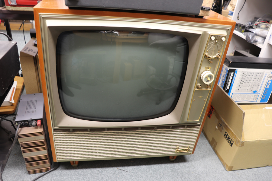
im into vintage electronics and have been restoring a few australian five valve radios and have finally decided to move on to trying to do the same to a valve television and thus when I came across this on eBay I couldn't resist.
I've opened it up to discover only three valves have been replaced since new. a 6BL8, 1S2 and the horizontal output which has its model number rubbed off. so it doesn't appear to be very high hour and the flyback is in brilliant shape. I've searched all over the internet and haven't been able to find the schematic for it and that's basically why I'm here is to see if anyone has a copy. and if anyone has anything else to help me out here it would be great.
now the original owner said they had plugged it in to discover no picture, which is no surprise.
so once it got it home and plugged it in figuring if it had already been turned on it won't harm it much running for a minute.
what I got was nice loud static coming from the speaker and I can hear the horizontal running! but alas no picture and no vertical as far as I can hear. the filament is glowing inside the CRT so it isn't dead I just have to figure out why there is no high voltage. maybe boost capacitor?
of coarse I have to do a full recap! I personally use 600v orange drop capacitors in this equipment and I've just ordered a bunch of values of 2kv rated capacitors just in case.
BTW how do you upload pictures as the link to the instructions gives me a 404 error.
Thanks
Lance
|
|
|
|
|

|
Location: Melbourne, VIC
Member since 20 September 2011
Member #: 1009
Postcount: 1263
|
Hello BurntOutElectronics.
If you want a Kriesler TV service manual I can help.
But you need to help me with a model number and/or a chassis type.
Once we know what it is I will post a pdf copy of the manual/schematic here.
|
|
|
|
|
|
|
Location: Melbourne, VIC
Member since 2 October 2019
Member #: 2392
Postcount: 284
|
Thanks for responding MonochromeTV
on the particle board on the back of the TV is missing the stamp where it should say the model number but looking inside the serial number tag says 79-10.
ive sent photos for upload
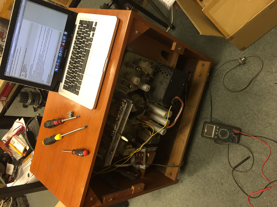
i was having a look at the back of the chassis as it can be swivelled out and later on I plugged it back in again only to jump 6 feet off the ground when a massive AC explosion came from the bottom of the set!
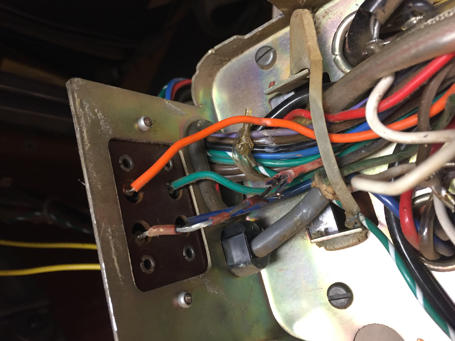
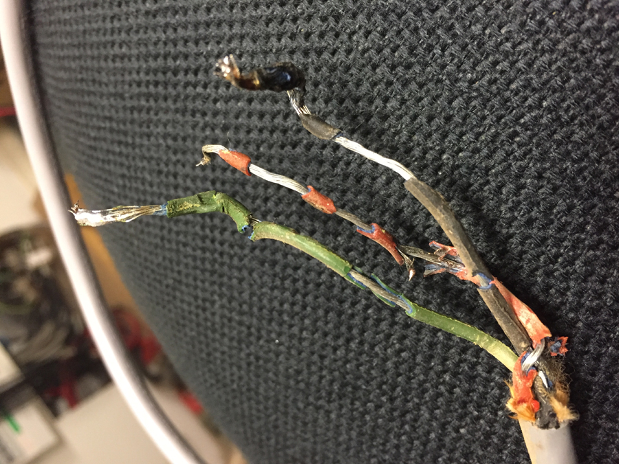
it turns out the swivel arm was a bit to sharp on the wires and broke the insulation on the primary side causing a dead short and the set to blow a 40A circuit breaker. I've uploaded the remains of the primary wire. this leaves me having to remove the whole thing tuner included which I probably had to do anyway but is a massive pain.
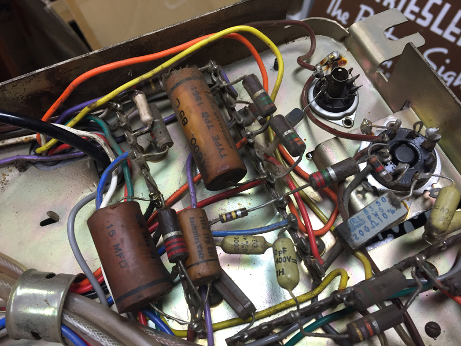
ive also noticed that there is a lot of mustard capacitors with only half a dozen paper capacitors so I don't know how mustard caps stand the test of time so if you know please tell.
thanks
lance
|
|
|
|
|

|
Location: Belrose, NSW
Member since 31 December 2015
Member #: 1844
Postcount: 2712
|
Those mustard coloured Philips caps are good news. DO NOT CHANGE THEM!!
Apart from accidental physical failures I've never seen a bad one. It's possible the remaining paper caps are in non-critical positions. Like a cathode bypass with 180 ohms across it, or the audio tone control circuit.
I've got the 79/10 circuit too if you email me. I'd send it to you if your email address were not hidden.
|
|
|
|
|

|
Administrator
Location: Naremburn, NSW
Member since 15 November 2005
Member #: 1
Postcount: 7633
|
BOE, e-mail your photos to me and I will upload them for you. Click on my username for the address. The site is in a bit of a transition mode at the moment, and there will still be a couple of broken links from when we shifted servers.
‾‾‾‾‾‾‾‾‾‾‾‾‾‾‾‾‾‾‾‾‾‾‾‾‾‾‾‾‾‾‾‾‾‾‾‾‾‾‾‾‾‾‾‾‾‾‾‾‾‾‾‾‾‾‾‾‾‾‾‾‾‾‾‾‾‾‾‾
A valve a day keeps the transistor away...
|
|
|
|
|
|
|
Location: Melbourne, VIC
Member since 2 October 2019
Member #: 2392
Postcount: 284
|
Brad ive sent some pictures to you let me know if you get them, thanks
i checked some of the mustard caps in circuit and I get some leakage on the micro amp scale on the leakage tester I built.
there is no question why I got a massive bang that popped the breaker earlier, I just took it further apart to discover the power cord is the early plastic type which has crumbled away to nothing!
luckily the rest of the set doesn't use this plastic!
my email is lw31_1_1989 hotmail.com hotmail.com
now the few paper caps inside are all in need of change as most are in the EHT circuit including a 1600v 0.056mfd cap that shows leakage at 30v!!!
almost nothing inside this set has been replaced but I don't have a tester to check any of the valves or the CRT so there condition is a mystery, oh well ill just have to wait and find out.
what do they use as an insulation layer inside those mustard caps?
thanks
|
|
|
|
|
|
|
Location: Melbourne, VIC
Member since 20 September 2011
Member #: 1009
Postcount: 1263
|
Models that use the 79-10 chassis are as follows:
121-70, Super Fringe Manual Console Grand.
121-71, Super Fringe Clockmatic Console Grand.
121-72, Super Fringe Manual Hi-Fi-Ette Wideline.
121-73, Super Fringe Clockmatic Hi-Fi Console .
121-79, Clockmatic R-TV-Stereo Theatre Super Fringe.
121-82, Manual Special Console Super Fringe.
|
|
|
|
|
|
|
Location: Melbourne, VIC
Member since 2 October 2019
Member #: 2392
Postcount: 284
|
Thanks for letting me know what models,
if I had to guest would be the first one as it isn't a clockmatic.
i check the voltage coming out of the flyback (with a screwdriver) and found its working but on the anode cap of the CRT there is nothing, nothing at all coming out of the 1S2. definitely some more head scratching to go before I get a picture.
i can't run the set for very long as the horizontal output gets screaming hot as id imagine that's because I haven't replaced any of the few paper caps but I have ordered them and this output valve is so baked that I'm really no bothered if it gets baked a little more while I find the problem with the EHT. I've got plenty more h. outputs anyway.
i must say when I get a schematic it will make life so much easier, thanks guys.
|
|
|
|
|
|
|
Location: Melbourne, VIC
Member since 20 September 2011
Member #: 1009
Postcount: 1263
|
|
|
|
|
|
|
|
Administrator
Location: Naremburn, NSW
Member since 15 November 2005
Member #: 1
Postcount: 7633
|
Photos uploaded to Post 1.
Documents uploaded to Post 9.
‾‾‾‾‾‾‾‾‾‾‾‾‾‾‾‾‾‾‾‾‾‾‾‾‾‾‾‾‾‾‾‾‾‾‾‾‾‾‾‾‾‾‾‾‾‾‾‾‾‾‾‾‾‾‾‾‾‾‾‾‾‾‾‾‾‾‾‾
A valve a day keeps the transistor away...
|
|
|
|
|
|
|
Location: Melbourne, VIC
Member since 2 October 2019
Member #: 2392
Postcount: 284
|
Well Brad and MonochromeTV
I don't know how to thank you enough! This is exactly the schematic I need and I would be absolutely stuffed without it!
And with instructions on how to do a full I.f. Alignment and a complete parts list will make it much easier to not only get parts but to also do a proper alignment which would be near impossible for me to figure out just by looking at it.
Thanks very much!
Lance
|
|
|
|
|
|
|
Administrator
Location: Naremburn, NSW
Member since 15 November 2005
Member #: 1
Postcount: 7633
|
Power cords are a big problem with vintage radios and televisions. The one in the picture is a bit of a hybrid as it uses a mix of the new and old way of doing things. The outer sheath is the expected grey PVC. One still needs to be careful with this as the chlorine separates from the rest of the plastic with age and it can attack and melt other plastics. In some cases, you can even smell the chlorine in it.
The cable insulation is VIR - Vulcanised Indian Rubber. It's not bad stuff when it's new and flexible cords are sometimes still made with it, particularly in the third world. With age though, it does perish and the PVC sheathing being in good condition can fool people into thinking that all parts of the cord are okay.
One of the first things I do when I restore a radio is that I just automatically cut off the old cord and replace it with a temporary one just made of a repurposed computer cable. IE: I snipped off the IEC plug and bared the ends for attachment to radios. This is then replaced with a proper brown cotton covered cable once the restoration work is done.
In picture 3, the cable gland looks like it can be re-used. In vintage radios I stick with grommets because that is usually what radio chassis were fitted with. In the case of your telly, sticking with that gland will keep it looking original. The grey cable keeper just to the right looks like it has perished though. A cable tie of the right size will easily replace that.
‾‾‾‾‾‾‾‾‾‾‾‾‾‾‾‾‾‾‾‾‾‾‾‾‾‾‾‾‾‾‾‾‾‾‾‾‾‾‾‾‾‾‾‾‾‾‾‾‾‾‾‾‾‾‾‾‾‾‾‾‾‾‾‾‾‾‾‾
A valve a day keeps the transistor away...
|
|
|
|
|
|
|
Location: Melbourne, VIC
Member since 2 October 2019
Member #: 2392
Postcount: 284
|
Yeah Brad I’ve installed a new grey power cable yesterday and the set powers on again without shorting.
I’ve noticed some of the resistors in the resistor divider network in the power supply have gone high resistance lowering the b+
And I checked the filament voltage on the 1S2 to (which is powered merely a coax type wire looped around the flyback) to be around 0.46VAC unloaded which is far too low as you’d know. Also the voltage coming off the fly back would only be a few kilovolt judging by the ark size. Obviously just about all of the resistors would be out of tolerance but I haven’t had a big eureka moment finding the main problem with the fly back. I’ve checked the voltage on the 6cm5 grid and that’s sitting at -37vdc as I’d expect the negative voltage won’t be as low when the b+ is lower. I guess the next step is replacing those resistors.
Lance
|
|
|
|
|
|
|
Location: Belrose, NSW
Member since 31 December 2015
Member #: 1844
Postcount: 2712
|
OK, you say the EHT transformer is getting hot.
A VERY common fault with these is shorted turns in the white epoxy EHT overwind. (connected to the top cap of the 1S2)
That would be why the 1S2 filament voltage is low as well.
A quick check:
With a well insulated screwdriver, you should be able to draw an arc of about 3 or 4 mm off the top cap of the 6CM5 (octal hor OP bottle) and at least 10mm or more off the cap of the 1S2. If the 1S2 arc is about the same as that from the 6CM5, the EHT overwind is shorted turns. Sadly, quite common.
The main reason these would fail is because the B+Boost pot was maladjusted by a numpty TV "tech". It should ONLY be adjusted by following the instructions on the circuit. Set it too high and the transformer WILL fail, eventually.
So you will need to find a new or good 2nd hand Philips NT3102 transformer. I have an older NT3101 in a parts chassis that can be made to work if you can't find the right one.
Forget about globally testing valves. In valve TVs the only reliable tester is the TV itself. In my experience you don't often need to replace them in TVs such as yours.
Here is a posting of mine that will help with the CRT testing.
https://vintage-radio.com.au/home.asp?f=6&th=201
In practice, if you get anything above half a volt with this test you will have a watchable picture. The health of the CRT is shown by how quickly the reading comes up, once it starts to move.
The 79-10 is a high-end model capable of excellent performance. But you will need to change those few paper caps and probably also the high-value resistors I see in the pic. Check them all.
Another tip:
Check what type of caps have been fitted in the C119 and C120 positions. These MUST be Styros or a similar zero temp co-efficient cap. The original styros will generally be light blue Ducons and they are OK. Dipped micas are good if you can get them in the capacitance you need, 8.2nF is a high value for a mica. If there are Mustards in C119 or C120 positions, they must be replaced - this is the only time you will ever need to change a mustard cap, they change capacitance slightly with temperature and throw the hor hold out of adjustment as the set warms up.
If you are not sure, post a pic and we'll tell you.
Your set looks like the Mustards are original, if so, good news.
|
|
|
|
|
|
|
Location: Melbourne, VIC
Member since 2 October 2019
Member #: 2392
Postcount: 284
|
G'day Ian!
It seams as I feared my nightmares have come true and my fly back is toast!
Coming off of the EHT it's the same length if anything the power coming off the 6cm5 packs more punch than the transformer!
Yikes I've had a bit of a look around and I haven't yet found a source for a replacement transformer! Aaah I knew it couldn't be THAT easy, that explains why the 6cm5 gets so hot when the flyback is internally shorted like that!
Explains why everything is so original obviously somebody else has been in here before me and must have given up but I'm a bit more stubborn than that and it will take more than a shorted trannie to make me give up.
Now...
I checked c119 & c120 and their both blue ducons
All of the capacitors are original! Every single one of them! I recon a set of this age being so original is a marvel in its own right.
I've noticed the voltage doubler diodes have been replaced with two AWV ones and a couple of resistors look replaced but other than that I can't find anything replace.
I'll try checking the CRT another day as it's too late now but it has reason to suggest that it should be a reasonably strong tube seeing the set was prematurely retired.
Thanks for the help Ian, really does mean a lot.
Lance
|
|
|
|
|
|
You need to be a member to post comments on this forum.
|