Welcome to Australia's only Vintage Radio and Television discussion forums. You are not logged in. Please log in below, apply for an account or retrieve your password.
Australian Vintage Radio Forums
  Home  ·  About Us  ·  Discussion Forums  ·  Glossary  ·  Outside Links  ·  Policies  ·  Services Directory  ·  Safety Warnings  ·  Tutorials

Member Introductions

Forum home - Go back to Member Introductions

 G'day Everyone and Kriesler Super fringe schematics
« Back · 1 · 2 · 3 · Next »
 Return to top of page · Post #: 16 · Written at 10:46:02 PM on 6 October 2019.
Ian Robertson's Gravatar
 Location: Belrose, NSW
 Member since 31 December 2015
 Member #: 1844
 Postcount: 2373

OK we are getting closer.

Unless Monochrome has one I doubt you'll find one of those trannys and they can't be repaired because the ferrite cores are glued with epoxy, using that nifty glass-beads-in-the-mix idea of Philips' to set the core gap.

Offer of the used NT3101 still stands..


 Return to top of page · Post #: 17 · Written at 8:21:25 PM on 7 October 2019.
BurntOutElectronics's Gravatar
 Location: Melbourne, VIC
 Member since 2 October 2019
 Member #: 2392
 Postcount: 269

Well Ian I will probably have to get yours but what's the price your offering for it?
And what would be the payment method?
Thanks
Lance


 Return to top of page · Post #: 18 · Written at 8:40:23 PM on 7 October 2019.
Vintage Pete's avatar
 Location: Albury, NSW
 Member since 1 May 2016
 Member #: 1919
 Postcount: 2048

Nice Kriesler you have there!!
Ohhh these 2 words we never mention, FB or CRT !! Hope you can sort it out as it looks good,,,,pete


 Return to top of page · Post #: 19 · Written at 8:44:22 AM on 8 October 2019.
BurntOutElectronics's Gravatar
 Location: Melbourne, VIC
 Member since 2 October 2019
 Member #: 2392
 Postcount: 269

I mean worst case scenario I may have to disconnect the high voltage winding and just make a voltage multiplyer for it but I would really like to steer away from that and keep it original.
I'm amazed by how much some of the people on this site know! Can I ask how long have some of you been doing this stuff?


 Return to top of page · Post #: 20 · Written at 5:00:30 PM on 8 October 2019.
Ian Robertson's Gravatar
 Location: Belrose, NSW
 Member since 31 December 2015
 Member #: 1844
 Postcount: 2373

I was a TV tech when I was in high school in the 60s. Made enough to buy my first car. Worked for a large service company while I did E&C Cert at night for about 10 years. Then started an electronics design company in 1976.

There wouldn't be many TVs I haven't seen before. Vintage TVs are a hobby of mine.

Re your suggestion, problem is, you'd have to remove the bad winding from the core for the tripler trick to work. Hacksaw, angle grinder, probable collateral damage. And you'll only get about 13500v max, which is a little low.

Re the NT3101, it's in an old KGH parts chassis. I believe it's OK but I'll have to strip it out and check. House painting at the moment, so this may take a while. Then I'll have to work out the necessary mods because the AFC/AGC winding on the 3101 is a lower voltage than that on the 3102.

Hopefully in the meantime you might find a suitable donor chassis with that transformer in it. Plessey-Rola made a clone of it for AWA-Thorn and it was used in the execrable last-of-the-B&W Thorn chassis, also badge engineered as AWA.


 Return to top of page · Post #: 21 · Written at 6:51:23 PM on 8 October 2019.
BurntOutElectronics's Gravatar
 Location: Melbourne, VIC
 Member since 2 October 2019
 Member #: 2392
 Postcount: 269

Wow Ian that explains why you know a staggering amount about this old valve gear.
I guess I might explain myself as well.
I’ve been on the soldering iron since I was about four years old (with my dad of course)
Anda couple of years ago I finally began to workout the world of thermionic emissions and valves in general. You see my dad was in his mid teens when everybody wanted to throw out valves and go germanium thus he has collected a few boxes of NOS valves from everywhere from run of the mill 6AU6 etc to some cool stuff like NOS military spec 807’s.
this of coarse has peaked my curiosity about the technology and I decided this year before I go into year 11 I’ll have a valve television project and that’s basically how I ended up with this Kriesler off eBay. It looked in good shape for its age and overall I’m very happy with it. I took a lot of convincing of my dad to finally let me get it with comments like ”where will you put it” and “what will you do with it” but anyway that’s a basic overview of how I came to find this site.
There is no need to rush and I doubt I’d find a donor chassis where I live. All the best
Lance


 Return to top of page · Post #: 22 · Written at 10:53:11 PM on 12 October 2019.
Ian Robertson's Gravatar
 Location: Belrose, NSW
 Member since 31 December 2015
 Member #: 1844
 Postcount: 2373

There are ways of using old TVs with DVD and other media players. I've posted on this site and there is an article in Silicon Chip that's my design.

They are great for watching old movies and TV programs.

Hopefully I'll be able to pull that transformer for you as part of the upcoming garage cleanup. No charge, just whatever it costs to get it to you.

Do check the CRT though. If it IS bad, all this may be for nothing - although I do have a 23" CRT in reasonable nick that should fit your set.

Email me so we can stay in touch!


 Return to top of page · Post #: 23 · Written at 9:11:31 PM on 16 March 2020.
BurntOutElectronics's Gravatar
 Location: Melbourne, VIC
 Member since 2 October 2019
 Member #: 2392
 Postcount: 269

G'day everyone

I've finally gotten back to working on the Kriesler TV and ive got A PICTURE!
i have tacked in the voltage multiplier Ian suggested I get and the TV has fantastic vertical and horizontal lock.

now my only problem is that the tripler doesn't give me enough EHT voltage thus the horizontal with is pulled in from the sides not filling the whole screen. so do I have to add another doubler stage? I'm trying to hunt down a HV probe for my multi meter to see what voltages are getting to the CRT but I know its not enough. anyones thoughts would be much appreciated.

Kriesler 79-10 Valve Television


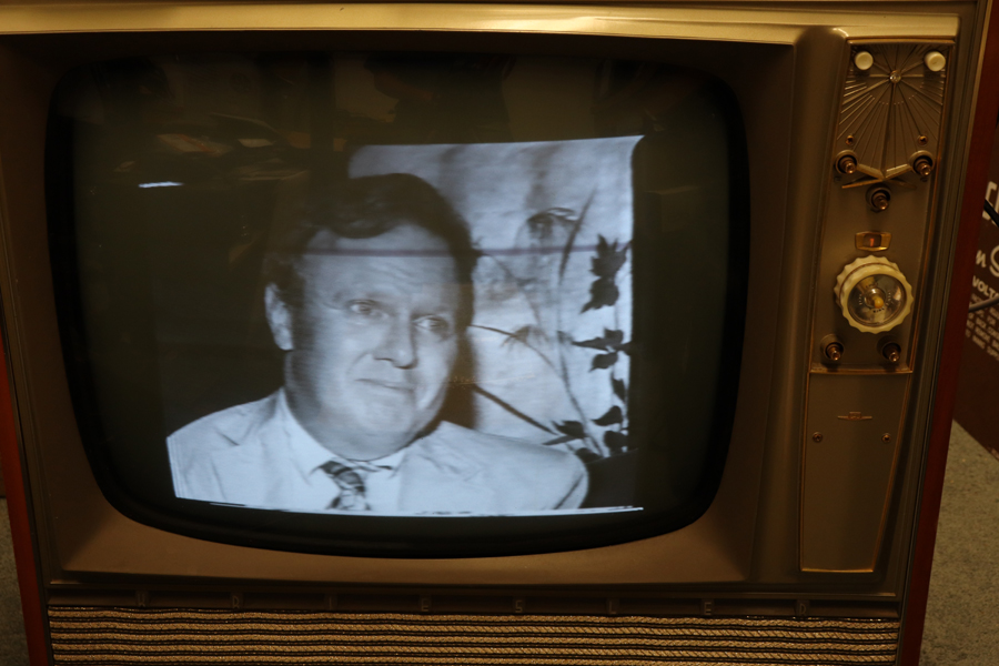
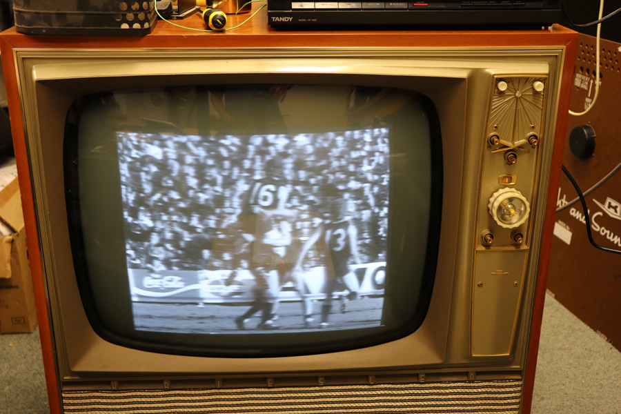
 Return to top of page · Post #: 24 · Written at 11:34:47 AM on 17 March 2020.
Ian Robertson's Gravatar
 Location: Belrose, NSW
 Member since 31 December 2015
 Member #: 1844
 Postcount: 2373

You really don't need a HV probe. Trust me!

Actually, if the width is insufficient, it usually means you have TOO MUCH EHT! With the higher voltage, the electron beam gets too "stiff" and harder to deflect. So, so far, good news!

Some things to check:

1. Did you set the B+Boost voltage correctly with the pot?
2. Did you replace the yoke coupler cap? If this 0.18μF cap is shorted it will reduce the width markedly and the picture will be squashed in the middle.. I notice that your set actually has a .15μF paper cap with another one in parallel. It looks like it;s been getting hot too

Here is a link to this part, back-ordered unfortunately:

https://au.element14.com/kemet/r76qr318050h3j/cap-aec-q200-0-18uf-1kv-film-radial/dp/3254654?st=.18uF

You can't just use any cap here, it carries a heavy current.

Does the width increase markedly if you turn the brightness up? If so, you may need to fit a bleed resistor to ground from the focus tap on the tripler. Without this resistor the voltage output of the tripler on low current draw increases quite a lot.

This is a somewhat special part, 47megohms or thereabouts, rated at at least 3 watts and about 5kV. A string of 10 x 4.7meg 1 watt resistors encased in plastic tubing is a possibility.

If the width does not increase with brightness you can add capacitance across the transformer to tune it down. now that the EHT winding has been removed. About 10 or 22pf ceramic cap rated at 5kV is needed. Again, a special part. Let me know if it's looking like this is needed. I just had a look and getting this voltage is a problem. Might have to use a lower tap.


 Return to top of page · Post #: 25 · Written at 3:43:49 PM on 17 March 2020.
BurntOutElectronics's Gravatar
 Location: Melbourne, VIC
 Member since 2 October 2019
 Member #: 2392
 Postcount: 269

Too much EHT? mmmh I’ll have to look into it a bit further.
When adjusting the b+boost trim pot only the intensity of the image is varied and not it’s size.
Changing the brightness makes the picture bloom and loose focus to a extent but it doesn’t really make it bigger.
I have changed all the paper caps in the TV. I think the part number from WES for the 0.15 cap was MEF.15 and is rated for 2Kv so hopefully is right for the job. The original .15 read about 15 ohms! Close enough to a dead short to me!
The current test connection to the tripler is U~ connected to the 6CM5 cap and A&D disconnected. So only effectively 5 diodes in circuit.
Initially I had a and D connected to the boost supply but it killed the HV
I’ve sent in pic to Brad so there should be images of what I’m getting on the TV soon


 Return to top of page · Post #: 26 · Written at 6:11:21 PM on 17 March 2020.
Ian Robertson's Gravatar
 Location: Belrose, NSW
 Member since 31 December 2015
 Member #: 1844
 Postcount: 2373

Interesting that the .15μF WAS shorted, that is probably what killed the transformer after a dodgy service tech maladjusted the B+boost pot to compensate. Not an unusual scenario unfortunately.

You should adjust it to get the 610 volts or whatever is recommended on the circuit. If you can't get that, there is another problem.

If you can, with some to spare, adding some capacitance across the yoke driver taps might do the trick. Start with .0047μF (4.7nF). Use the physically biggest 4.7nF cap you can find, anything too small will only last a few seconds.

You could also try shorting out the "linearity mouse" (you'll know what I mean when you see it).


 Return to top of page · Post #: 27 · Written at 6:44:09 PM on 17 March 2020.
BurntOutElectronics's Gravatar
 Location: Melbourne, VIC
 Member since 2 October 2019
 Member #: 2392
 Postcount: 269

I’ll align the trim pot for the B+Boost but
Which are the yolk driver taps? I know I probably sound quite dense saying that but this is my first valve TV.
I actually still have the original .15 cap around here but yes it is shorted.
One thing I haven’t quite managed to figure out is how a voltage multiplier works without a reference to ground!
From what I can tell when the 16 or so kHz pulse is positive it passes straight through the diodes but when it turns negative it flows backwards charging the capacitors for when it turns positive again. But why does it use 5 diodes and not 4? I don’t play around with HV stuff enough to get my head around all of it.


 Return to top of page · Post #: 28 · Written at 9:07:32 PM on 18 March 2020.
Ian Robertson's Gravatar
 Location: Belrose, NSW
 Member since 31 December 2015
 Member #: 1844
 Postcount: 2373

Hey, a lot to cover in this session! I've got access to my schematics again.

The yoke (like the thing that goes round the neck of an ox - get it?) taps are pins 4 and 6 on T6. You will see they connect to the yoke via C136 on one end, and L20 (the horizontal linearity saturable reactor) on the other.

I notice there's an option to disconnect C138 by removing a wire link on the yoke plug. See the note just below T6. With C138 out of circuit, the yoke coupler cap is just C136, the 0.15μF. That will increase the width. Counterintuitive, but true!

The voltage multiplier reference point I suggested is the BHT connection. My thinking is that would lift the reference and hence the final output by about 850 volts. In AC terms it's still ground.

Not sure why the 5th diode.

Oh, when you removed the EHT winding, did you cut it off or did you separate the ferrite core halves? If the latter, you might have altered the air gap between the core halves and that will affect the EHT and width.

So......

Try cutting the link first as per the schematic. If that doesn't make enough extra width, try adding capacitance between pins 4 and 6 of T6.


 Return to top of page · Post #: 29 · Written at 9:56:48 PM on 18 March 2020.
BurntOutElectronics's Gravatar
 Location: Melbourne, VIC
 Member since 2 October 2019
 Member #: 2392
 Postcount: 269

Thanks for walking me through this. There’s only so much time I get to learn about all this when I’ve got school work to shovel through first.
When I removed the EHT winding I just cut it off I didn’t separated the two halves. I’ll try jumping out the 2nd cap tomorrow and we’ll see how I go


 Return to top of page · Post #: 30 · Written at 1:25:09 PM on 19 March 2020.
Ian Robertson's Gravatar
 Location: Belrose, NSW
 Member since 31 December 2015
 Member #: 1844
 Postcount: 2373

Removing the EHT winding would have reduced the total winding capacitance somewhat, so adding capacitance will help.
The aim is to tune the yoke and transformer combination to either the 3rd or the 5th harmonic of the scan frequency. This gives best efficiency.

The 0.15μF cap in series with the yoke does something similar. It forms a series tuned circuit. The sine wave component thus generated adds "S correction" to the sawtooth current scan waveform.

S correction is needed for wide deflection angle CRTs because the target (the screen) is closer to the gun in the middle of the scan. So,as it scans across the screen, the angular velocity of the beam has to speed up in the middle and slow down at the sides. If this were not done the picture would be squashed in the middle.

The reason your TV has that jumper on the yoke plug is this. The standard Philips CRT had 110 degree deflection angle. The was an alternative CRT, Thomas 23WP4, that had 114 degree deflection. So the S correction needed was different.

If you have been paying attention, you might ask "what about when the beam is scanning the top and the bottom of the screen? Won't the amount of correction be different?"

The answer is of course, yes.

What is normally done is a compromise that is tuned to two points, 1/3 and 2/3 of the way down the screen.

The first Kriesler colour TVs actually had a circuit that modulated this S correction so that it was accurate over the whole screen. The similar Philips TVs left these parts out as a cost saving exercise.

Ah, the joys of analogue design!! So much easier these days when all you have is a giant shift register!


« Back · 1 · 2 · 3 · Next »
 You need to be a member to post comments on this forum.

Sign In

Username:
Password:
 Keep me logged in.
Do not tick box on a computer with public access.