
Tech Talk
Forum home - Go back to Tech talk
|
Astor Mickey OZ circuit variations over the production period, 1933 – 1935
|
|
|
Return to top of page · Post #: 1 · Written at 12:09:40 PM on 19 August 2018.
|
|

|
Location: Perth, WA
Member since 19 November 2008 Member #: 381 Postcount: 240 |
|
I am restoring my OZ and have noticed some circuit differences to the published schematic. |
|
|
Return to top of page · Post #: 2 · Written at 12:10:40 PM on 19 August 2018.
|
|
|
|
Location: Perth, WA
Member since 19 November 2008 Member #: 381 Postcount: 240 |
|
Astor OZ Original Schematic: |
|
|
Return to top of page · Post #: 3 · Written at 12:32:09 PM on 19 August 2018.
|
|
|
|
Location: Perth, WA
Member since 19 November 2008 Member #: 381 Postcount: 240 |
|
Serial Number 3381 Pictures: 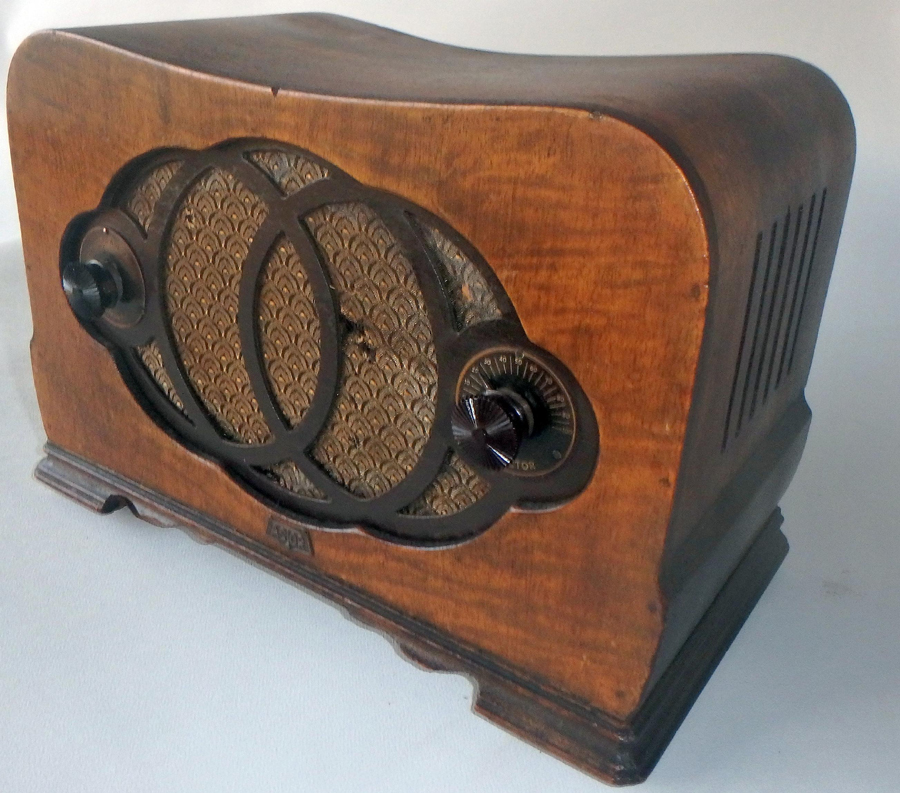 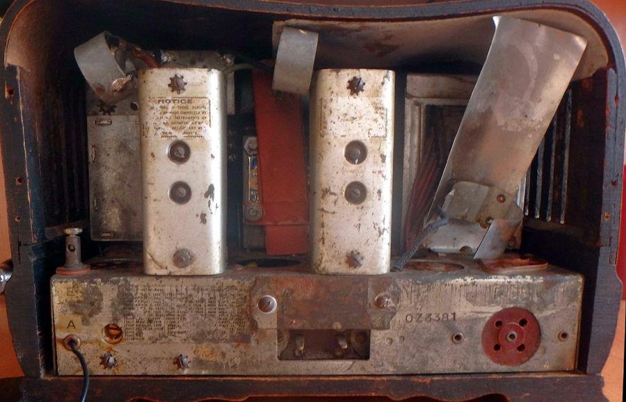 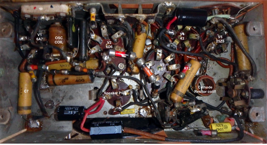 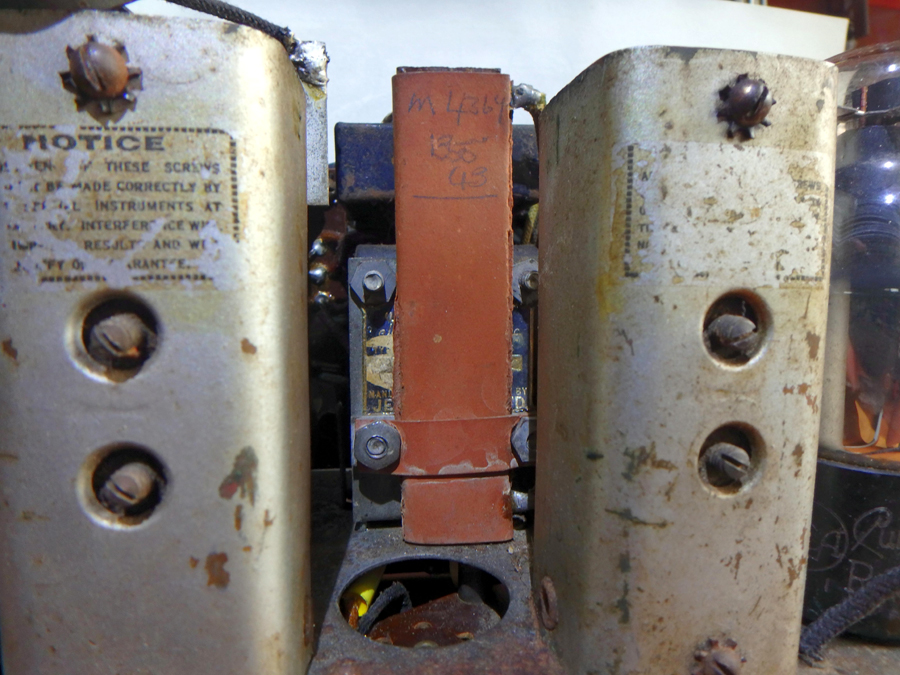 |
|
|
Return to top of page · Post #: 4 · Written at 9:25:38 PM on 19 August 2018.
|
|

|
Administrator
Location: Naremburn, NSW
Member since 15 November 2005 Member #: 1 Postcount: 7624 |
|
Photos and documents uploaded. ‾‾‾‾‾‾‾‾‾‾‾‾‾‾‾‾‾‾‾‾‾‾‾‾‾‾‾‾‾‾‾‾‾‾‾‾‾‾‾‾‾‾‾‾‾‾‾‾‾‾‾‾‾‾‾‾‾‾‾‾‾‾‾‾‾‾‾‾ A valve a day keeps the transistor away... |
|
|
Return to top of page · Post #: 5 · Written at 11:44:37 AM on 20 August 2018.
|
|
|
|
Location: Perth, WA
Member since 19 November 2008 Member #: 381 Postcount: 240 |
|
Observations on the OZ radio in the Silicon Chip article, Serial Number 5753. |
|
|
Return to top of page · Post #: 6 · Written at 11:48:23 AM on 20 August 2018.
|
|
|
|
Location: Perth, WA
Member since 19 November 2008 Member #: 381 Postcount: 240 |
|
Observations on OZ radio Serial Number 7672. 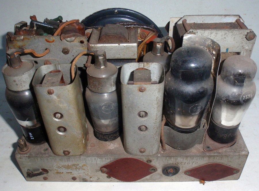 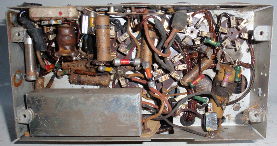 |
|
|
Return to top of page · Post #: 7 · Written at 12:35:38 AM on 21 August 2018.
|
|
|
|
Administrator
Location: Naremburn, NSW
Member since 15 November 2005 Member #: 1 Postcount: 7624 |
|
Photos uploaded to Post 6. ‾‾‾‾‾‾‾‾‾‾‾‾‾‾‾‾‾‾‾‾‾‾‾‾‾‾‾‾‾‾‾‾‾‾‾‾‾‾‾‾‾‾‾‾‾‾‾‾‾‾‾‾‾‾‾‾‾‾‾‾‾‾‾‾‾‾‾‾ A valve a day keeps the transistor away... |
|
|
Return to top of page · Post #: 8 · Written at 3:10:46 PM on 21 August 2018.
|
|

|
Location: Wangaratta, VIC
Member since 21 February 2009 Member #: 438 Postcount: 5715 |
|
I see with one of those, a hole drilled for a cable. I wonder if an IEC socket would fit in that original hole? The transformer is shown as "shielded" & they always bleed charge onto a chassis, an earth wire would get rid of it. |
|
|
Return to top of page · Post #: 9 · Written at 3:52:10 PM on 21 August 2018.
|
|
|
|
Location: Belrose, NSW
Member since 31 December 2015 Member #: 1844 Postcount: 2710 |
|
I've always thought the use of the 25Z5 rectifier in the Mickey was intriguing. |
|
|
Return to top of page · Post #: 10 · Written at 8:23:33 PM on 21 August 2018.
|
|
|
|
Location: Wangaratta, VIC
Member since 21 February 2009 Member #: 438 Postcount: 5715 |
|
25Z5 pre-dates 6X5 by 3 years. 6X5 was designed for car radio's originally, which was interesting as some mechanical variants of it, were notorious (from info on the American forum, particularly in Zenith radios) for heater cathode shorts & the impending destruction of transformers when they did. |
|
|
Return to top of page · Post #: 11 · Written at 9:13:52 AM on 22 August 2018.
|
|
|
|
Location: Belrose, NSW
Member since 31 December 2015 Member #: 1844 Postcount: 2710 |
|
Yes the well-known 6X5 heater snake. Looks quite alarming when you first see it but it usually doesn't stop the valve from working... |
|
|
Return to top of page · Post #: 12 · Written at 9:49:41 AM on 22 August 2018.
|
|
|
|
Location: Belrose, NSW
Member since 31 December 2015 Member #: 1844 Postcount: 2710 |
|
Getting back to the strange choice of the 25Z5, the 6Z4 (84) was available at that time and had a 6.3v heater. |
|
|
Return to top of page · Post #: 13 · Written at 10:51:40 AM on 22 August 2018.
|
|
|
|
Location: Perth, WA
Member since 19 November 2008 Member #: 381 Postcount: 240 |
|
The 25Z5 was used in most Astor's in 1933, 34. |
|
|
Return to top of page · Post #: 14 · Written at 1:24:45 PM on 22 August 2018.
|
|
|
|
Location: Belrose, NSW
Member since 31 December 2015 Member #: 1844 Postcount: 2710 |
|
Maybe they had acquired a stash of them in readiness for a hot chassis version that never eventuated. Happens..... |
|
|
Return to top of page · Post #: 15 · Written at 6:32:03 PM on 22 August 2018.
|
|
|
|
Location: Perth, WA
Member since 19 November 2008 Member #: 381 Postcount: 240 |
|
The Silicon Chip article states under Australian modifications. |
|
|
You need to be a member to post comments on this forum.
|
|
Sign In
Vintage Radio and Television is proudly brought to you by an era where things were built with pride and made to last.
DISCLAIMER: Valve radios and televisions contain voltages that can deliver lethal shocks. You should not attempt to work on a valve radio or other electrical appliances unless you know exactly what you are doing and have gained some experience with electronics and working around high voltages. The owner, administrators and staff of Vintage Radio & Television will accept no liability for any damage, injury or loss of life that comes as a result of your use or mis-use of information on this website. Please read our Safety Warning before using this website.
WARNING: Under no circumstances should you ever apply power to a vintage radio, television or other electrical appliance you have acquired without first having it checked and serviced by an experienced person. Also, at no time should any appliance be connected to an electricity supply if the power cord is damaged. If in doubt, do not apply power.
Shintara - Keepin' It Real · VileSilencer - Maintain The Rage