
Tech Talk
Forum home - Go back to Tech talk
|
Astor Mickey OZ circuit variations over the production period, 1933 – 1935
|
|
|
Return to top of page · Post #: 16 · Written at 12:49:13 PM on 23 August 2018.
|
|
|
|
Location: Belrose, NSW
Member since 31 December 2015 Member #: 1844 Postcount: 2372 |
|
Astor made a few hot chassis designs. |
|
|
Return to top of page · Post #: 17 · Written at 2:33:07 PM on 23 August 2018.
|
|

|
Location: Hobart, TAS
Member since 31 July 2016 Member #: 1959 Postcount: 544 |
|
Not to mention the poor antenna installers. |
|
|
Return to top of page · Post #: 18 · Written at 4:19:11 PM on 23 August 2018.
|
|
|
|
Location: Belrose, NSW
Member since 31 December 2015 Member #: 1844 Postcount: 2372 |
|
Yes I can imagine! |
|
|
Return to top of page · Post #: 19 · Written at 3:30:17 PM on 26 August 2018.
|
|

|
Location: Beechmont, QLD
Member since 10 April 2009 Member #: 465 Postcount: 109 |
|
I believe that Astor had originally designed the OZ as a hot chassis set, or at least a transformerless set. However, testing proved that getting rid of the extra heat with 240 volt mains in an Australian summer was problematic and the radio had a transformer added for production. |
|
|
Return to top of page · Post #: 20 · Written at 3:55:55 PM on 26 August 2018.
|
|
|
|
Location: Belrose, NSW
Member since 31 December 2015 Member #: 1844 Postcount: 2372 |
|
Yes I once had a really tiny 5 valve pink plastic radio that was basically a Japan / US design, modified to sell in (I think) Hong Kong. |
|
|
Return to top of page · Post #: 21 · Written at 9:37:58 PM on 26 August 2018.
|
|

|
Administrator
Location: Naremburn, NSW
Member since 15 November 2005 Member #: 1 Postcount: 7304 |
|
Here are my promised photos. I believe this is receiver number OZ4185 but I will check with the naked eye tomorrow instead of just maxing out the chassis photo because it is inconclusive. 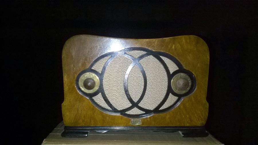 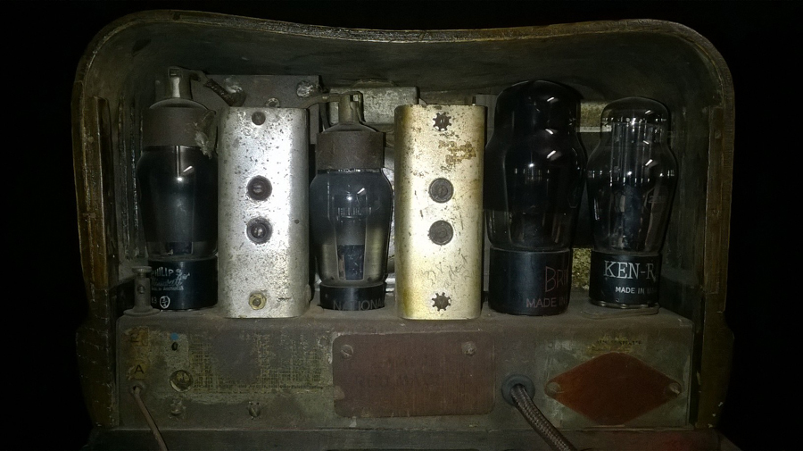   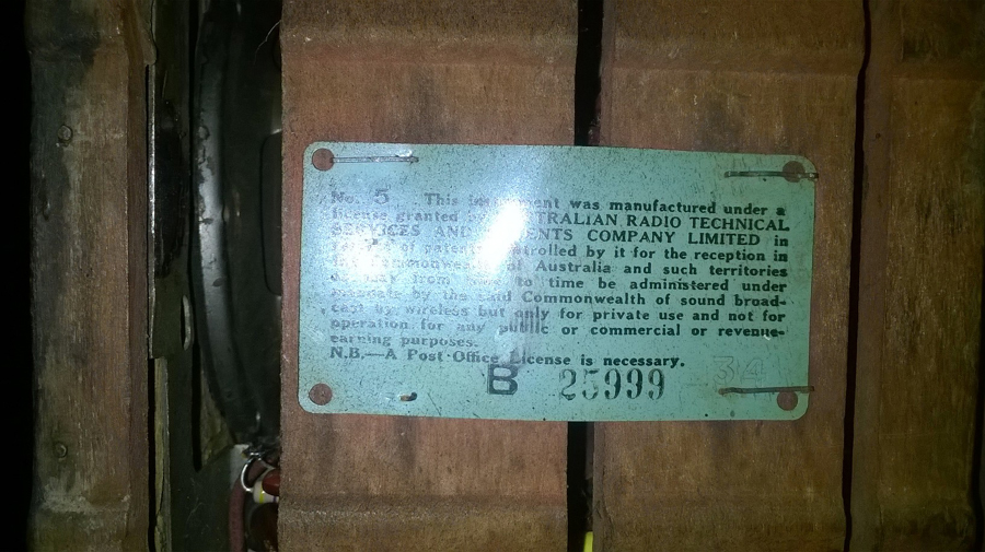 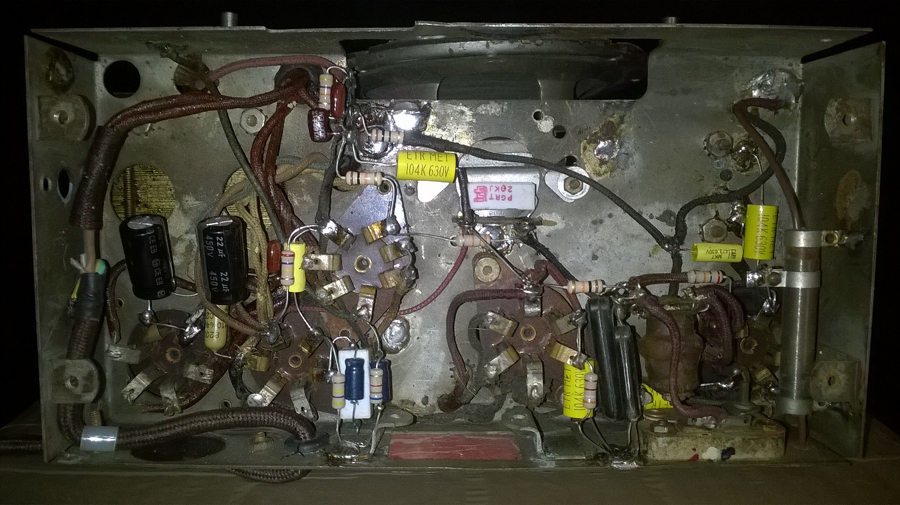 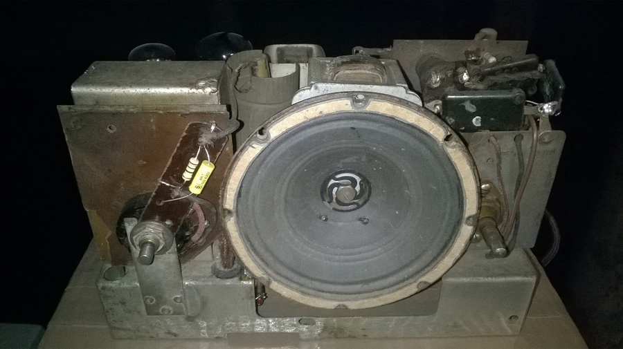 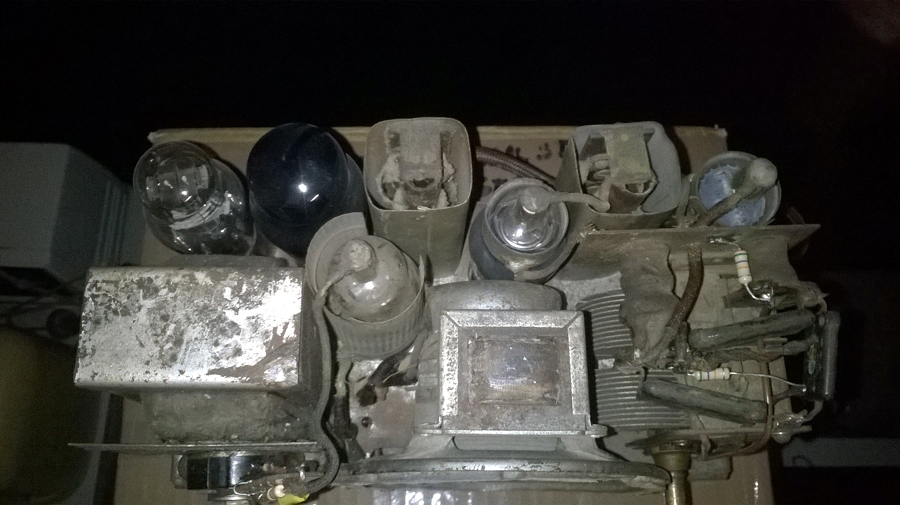 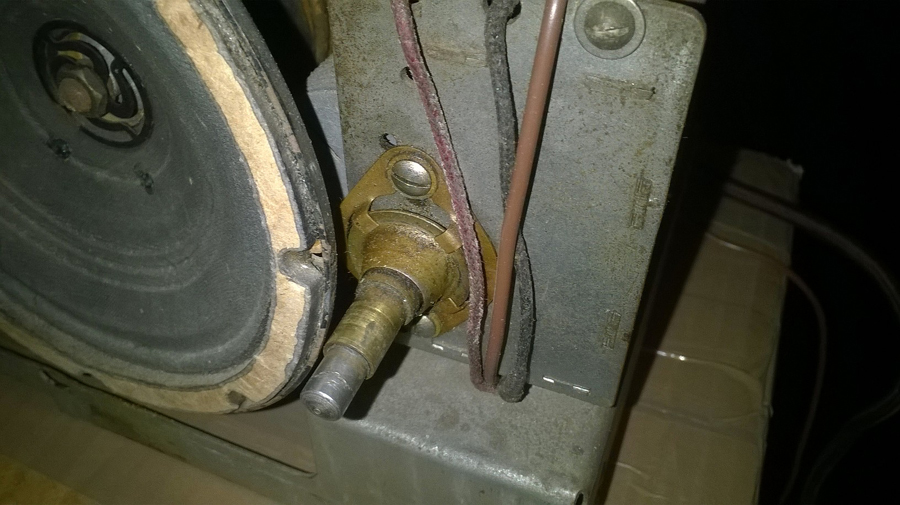 More to come. By the way: I am happy to lift the image posting limit for this thread. Within reason, this will be unlimited. ‾‾‾‾‾‾‾‾‾‾‾‾‾‾‾‾‾‾‾‾‾‾‾‾‾‾‾‾‾‾‾‾‾‾‾‾‾‾‾‾‾‾‾‾‾‾‾‾‾‾‾‾‾‾‾‾‾‾‾‾‾‾‾‾‾‾‾‾ A valve a day keeps the transistor away... |
|
|
Return to top of page · Post #: 22 · Written at 11:34:43 AM on 2 September 2018.
|
|

|
Location: Perth, WA
Member since 19 November 2008 Member #: 381 Postcount: 240 |
|
Hi Brad, 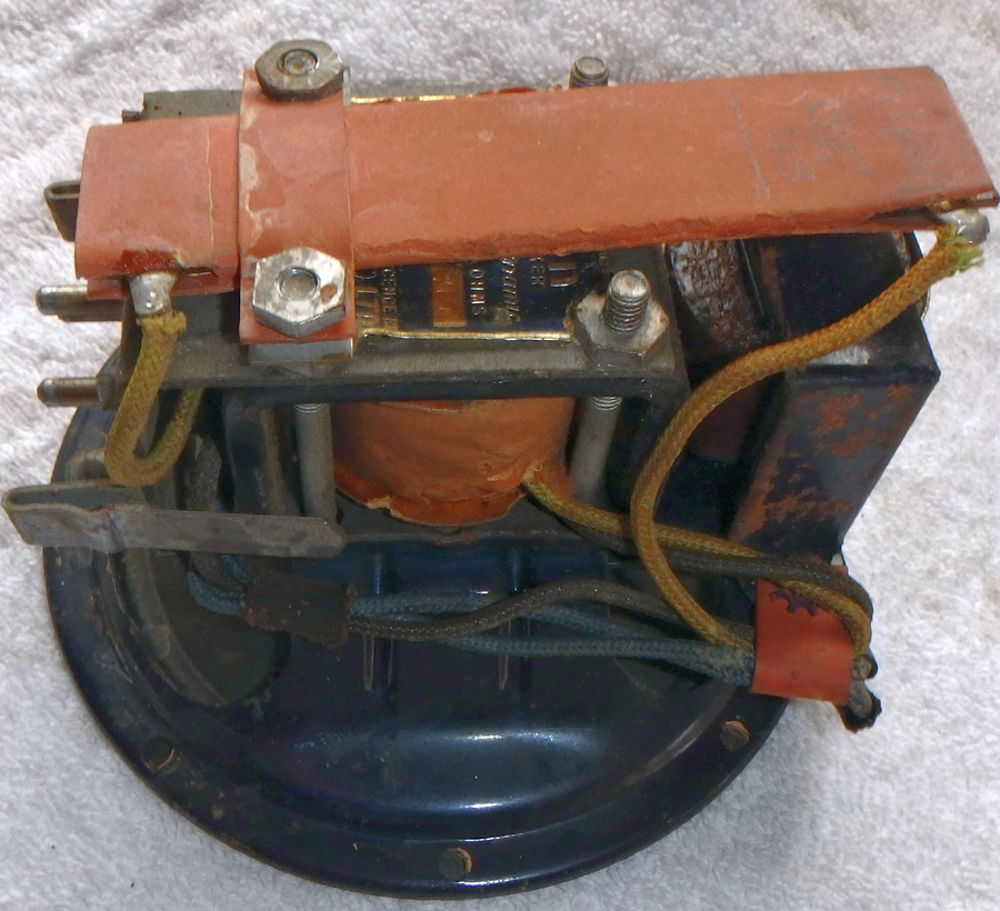 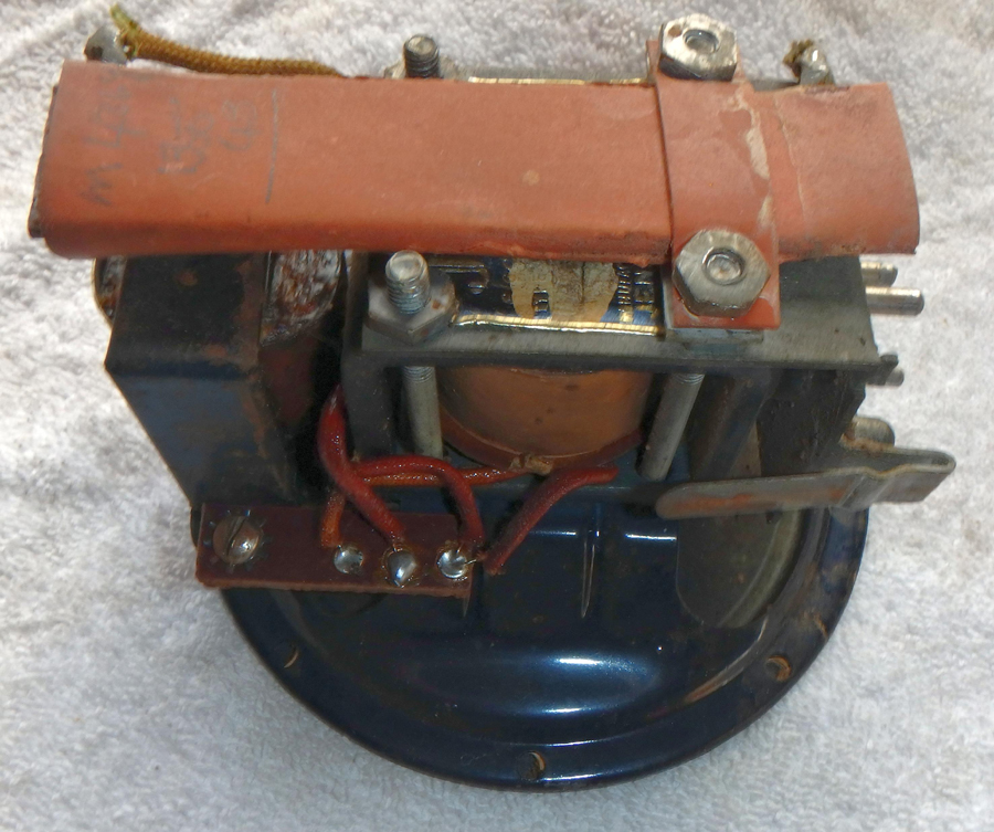 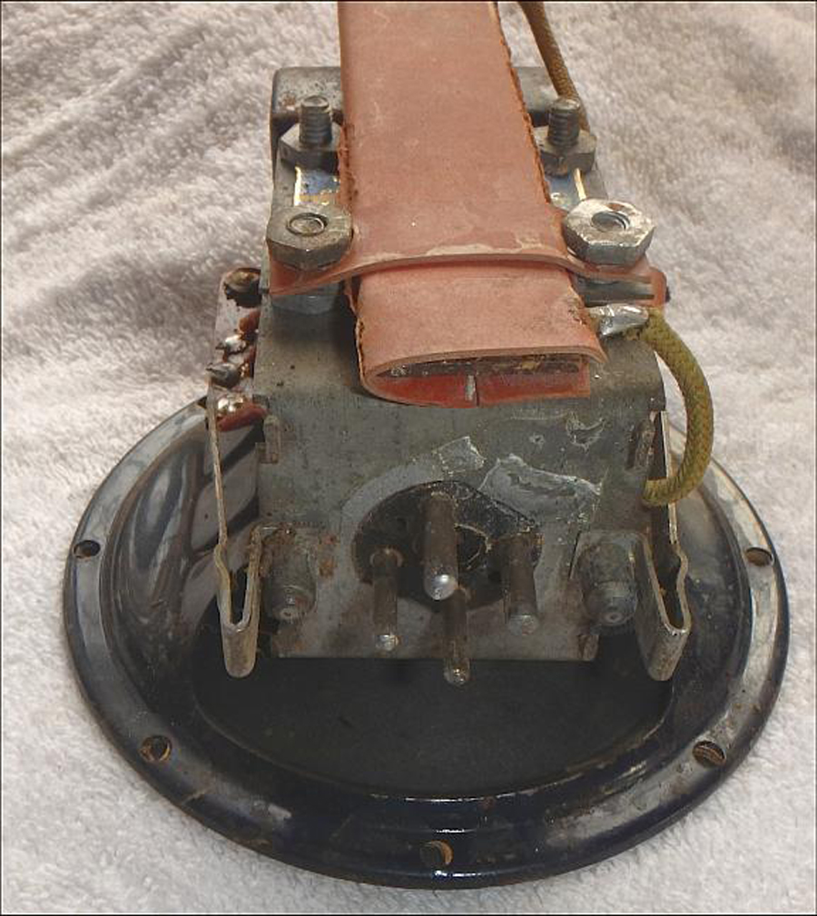 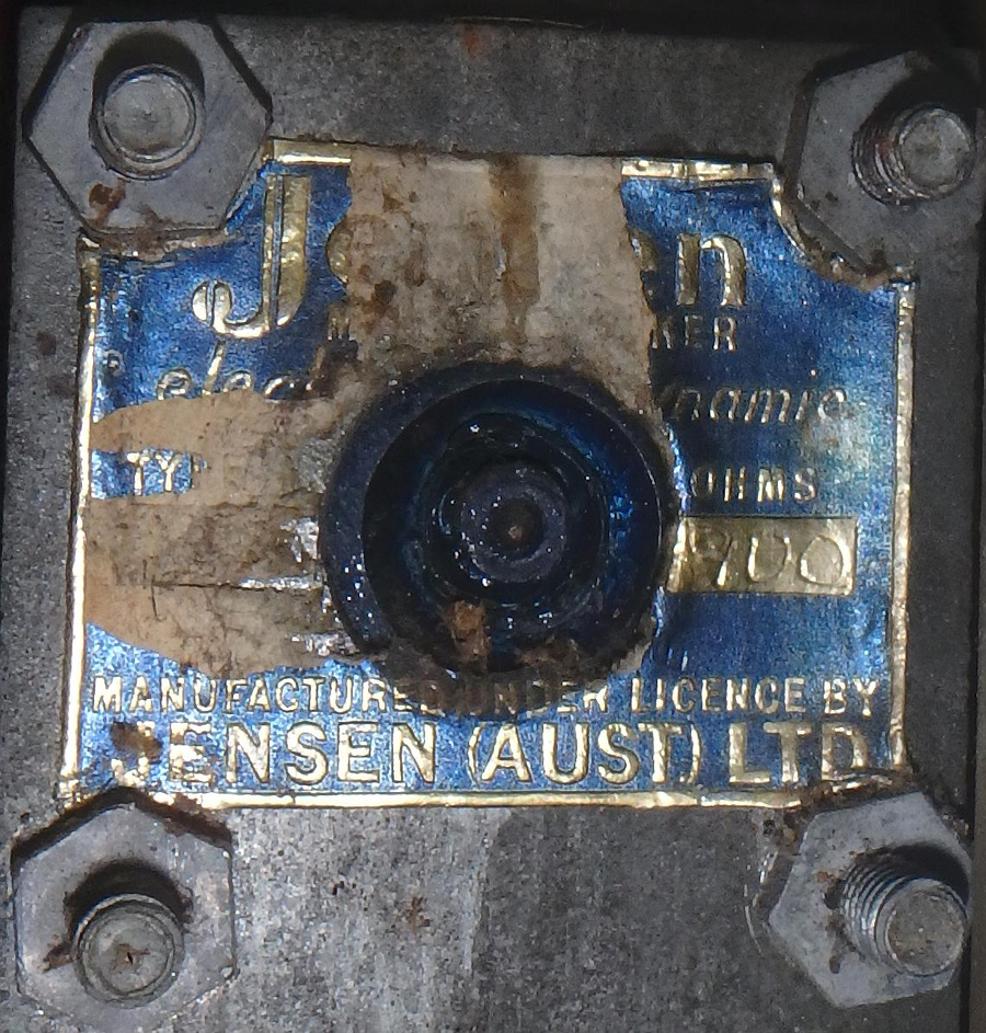 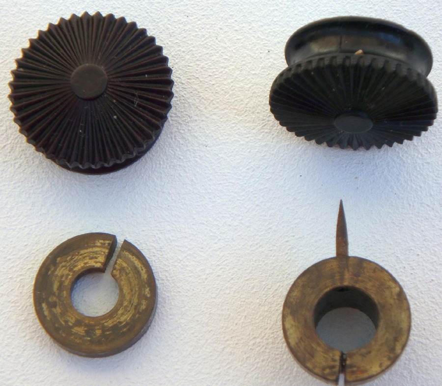 Does anyone else have an early serial number radio? See post below for details of the speaker change over switch and knob. https://vintage-radio.com.au/default.asp?f=1&th=1352 Cheers, Gary |
|
|
Return to top of page · Post #: 23 · Written at 3:48:22 PM on 2 September 2018.
|
|
|
|
Location: NSW
Member since 10 June 2010 Member #: 681 Postcount: 1256 |
|
For the record mine is OZ7522. |
|
|
Return to top of page · Post #: 24 · Written at 11:55:16 PM on 3 September 2018.
|
|
|
|
Administrator
Location: Naremburn, NSW
Member since 15 November 2005 Member #: 1 Postcount: 7304 |
|
Photos uploaded to Post 22. ‾‾‾‾‾‾‾‾‾‾‾‾‾‾‾‾‾‾‾‾‾‾‾‾‾‾‾‾‾‾‾‾‾‾‾‾‾‾‾‾‾‾‾‾‾‾‾‾‾‾‾‾‾‾‾‾‾‾‾‾‾‾‾‾‾‾‾‾ A valve a day keeps the transistor away... |
|
|
Return to top of page · Post #: 25 · Written at 11:16:06 AM on 4 September 2018.
|
|
|
|
Location: Perth, WA
Member since 19 November 2008 Member #: 381 Postcount: 240 |
|
STC830, does serial number OZ7522 have the change over switch and extension socket on the rear of the chassis. |
|
|
Return to top of page · Post #: 26 · Written at 5:27:46 PM on 4 September 2018.
|
|
|
|
Location: NSW
Member since 10 June 2010 Member #: 681 Postcount: 1256 |
|
"does serial number OZ7522 have the change over switch and extension socket on the rear of the chassis." 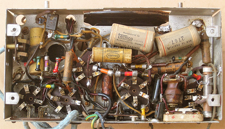 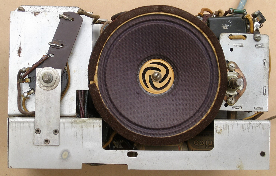 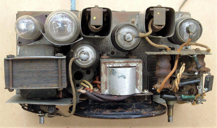 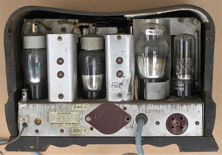 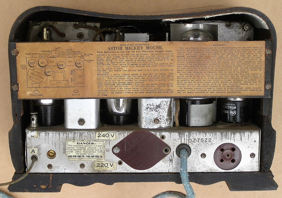 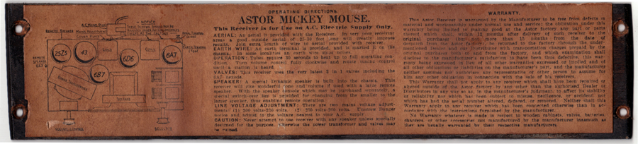 These comments are added as an edit to the post to explain the newly added photographs (thanks Brad). The comments are numbered in the order of the photographs . 1. Under the chassis. The 43 socket is second socket from the left. The rightmost tag is for pin 5 and is tied directly to earth; no sign of a cathode bias resistor or its bypass cap. At the left of the chassis are the extension speaker socket and speaker changeover switch; connections are removed. At the right of the chassis the wirewound resistor has been modified by the addition of a wire tap. The bottom part of the wire coil is broken and the top part is detached from the top tag of the resistor. The length of the active part of the coil is about 13mm and has a resistance of 213ohm. The total length of the coil is about 42mm from which the total resistance of the wirewound resistor is estimated to be about 690ohm. The 213ohm part appears to be the cathode bias resistor for the 6A7 below it. 2. Front of the chassis showing bakelite sheet behind the volume control also mentioned in 3. 3. Top of the chassis. Behind the volume control is a bakelite sheet carrying a resistor and capacitor. The twisted wires on top of the tuning gang are not soldered at the free end and appear to be a very low value cap as part of the oscillator. 4. Back without backbar. There is no resistor tied to the back of the speaker. 5. Back of the OZ with the backbar attached. Extension speaker socket at the right hand end of the back of the chassis. Behind the bakelite sheet cover is the mains voltage changeover consisting of two screw terminals and the fly lead which is changed over. 6. A scan of the backboard label. This is a 5.2Mb jpg file and hasn't been processed to improve clarity. This is for anyone who wants to reproduce it and do their own enhancements. Can email the original file to anyone who needs it. In summary the radio appears to have been original to the published circuit before it was "got at" at the wirewound resistor and extension speaker circuitry. Various apparently resoldered joints hint at other possible modifications so that this radio is not ideal for devining circuit changes over time. That said, all components appear to be period originals. |
|
|
Return to top of page · Post #: 27 · Written at 6:35:33 PM on 10 September 2018.
|
|
|
|
Location: Perth, WA
Member since 19 November 2008 Member #: 381 Postcount: 240 |
|
Here is the text from the backbar of the OZ Radio. |
|
|
Return to top of page · Post #: 28 · Written at 8:23:56 PM on 11 September 2018.
|
|
|
|
Administrator
Location: Naremburn, NSW
Member since 15 November 2005 Member #: 1 Postcount: 7304 |
|
Photos uploaded to Post 26. ‾‾‾‾‾‾‾‾‾‾‾‾‾‾‾‾‾‾‾‾‾‾‾‾‾‾‾‾‾‾‾‾‾‾‾‾‾‾‾‾‾‾‾‾‾‾‾‾‾‾‾‾‾‾‾‾‾‾‾‾‾‾‾‾‾‾‾‾ A valve a day keeps the transistor away... |
|
|
Return to top of page · Post #: 29 · Written at 7:48:42 AM on 12 September 2018.
|
|
|
|
Location: NSW
Member since 10 June 2010 Member #: 681 Postcount: 1256 |
|
Regarding post 26, I didn't notice that Brad had rearranged the photos in a better order, so that my prewritten comments which I had pasted in also needed to be reordered. This accounts for the editing of the comments in post 26, along with other minor corrections. |
|
|
Return to top of page · Post #: 30 · Written at 10:06:33 AM on 12 September 2018.
|
|
|
|
Administrator
Location: Naremburn, NSW
Member since 15 November 2005 Member #: 1 Postcount: 7304 |
|
Slight accident on my part there - as I usually just include photos in the order they are pasted to Outlook. If you want the comments put after each photo, let me know and I'll change the HTML to suit. ‾‾‾‾‾‾‾‾‾‾‾‾‾‾‾‾‾‾‾‾‾‾‾‾‾‾‾‾‾‾‾‾‾‾‾‾‾‾‾‾‾‾‾‾‾‾‾‾‾‾‾‾‾‾‾‾‾‾‾‾‾‾‾‾‾‾‾‾ A valve a day keeps the transistor away... |
|
|
You need to be a member to post comments on this forum.
|
|
Sign In
Vintage Radio and Television is proudly brought to you by an era where things were built with pride and made to last.
DISCLAIMER: Valve radios and televisions contain voltages that can deliver lethal shocks. You should not attempt to work on a valve radio or other electrical appliances unless you know exactly what you are doing and have gained some experience with electronics and working around high voltages. The owner, administrators and staff of Vintage Radio & Television will accept no liability for any damage, injury or loss of life that comes as a result of your use or mis-use of information on this website. Please read our Safety Warning before using this website.
WARNING: Under no circumstances should you ever apply power to a vintage radio, television or other electrical appliance you have acquired without first having it checked and serviced by an experienced person. Also, at no time should any appliance be connected to an electricity supply if the power cord is damaged. If in doubt, do not apply power.
Shintara - Keepin' It Real · VileSilencer - Maintain The Rage