|
Restoring an AWA Radiola 517M
|
|
|
|
|

|
Location: Lalor Park, NSW
Member since 7 April 2018
Member #: 2237
Postcount: 57
|
Hi all,
This is a first of many posts as I go about restoring my first AWA Radiola 517-M.
I will undoubtably have a few questions, and all feedback is greatly appreciated 
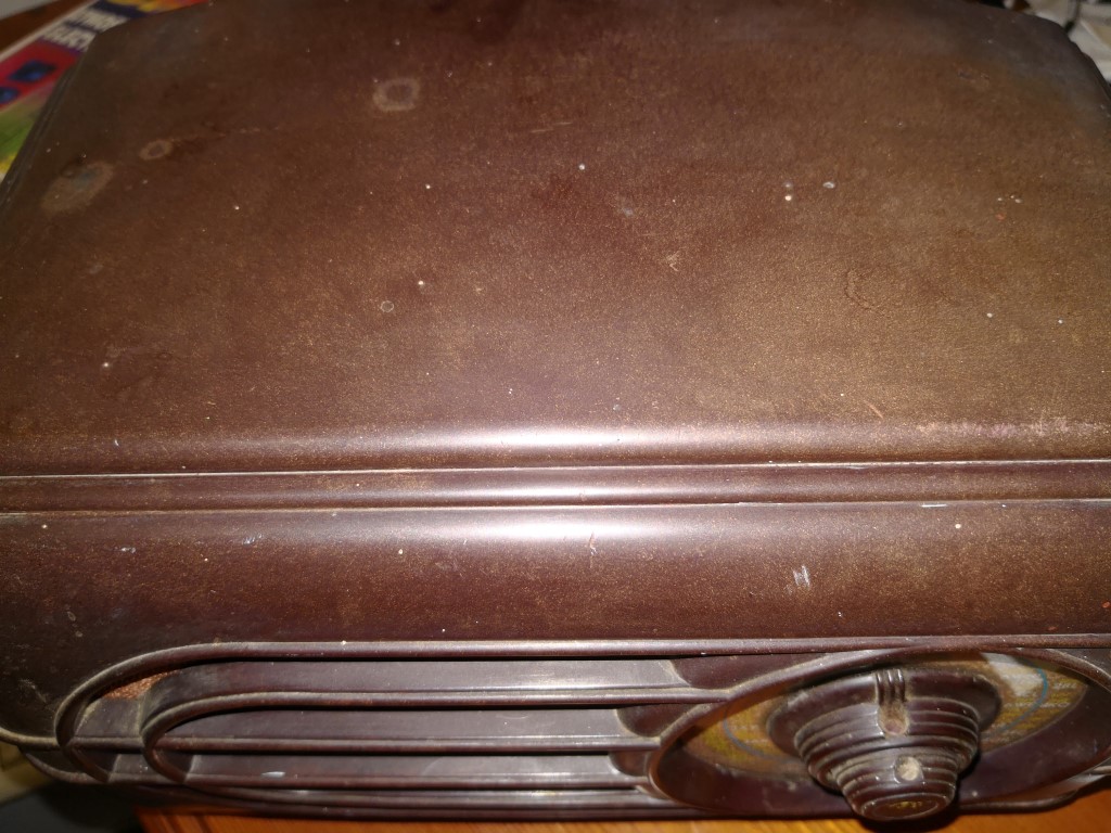
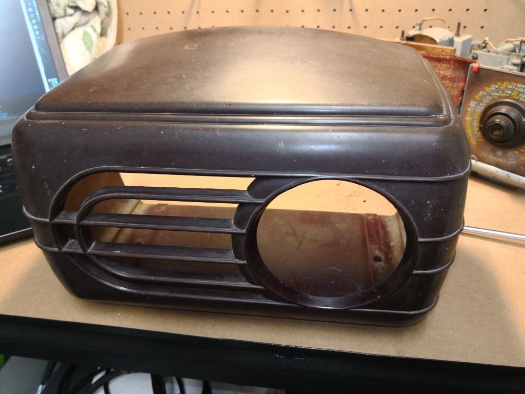
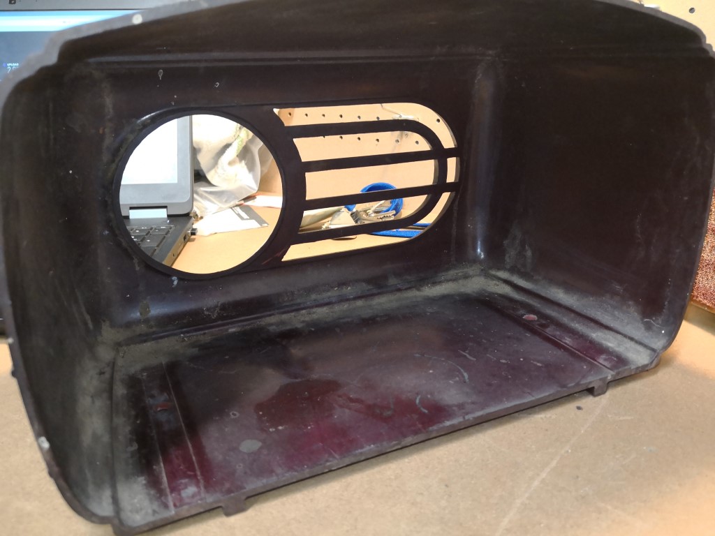
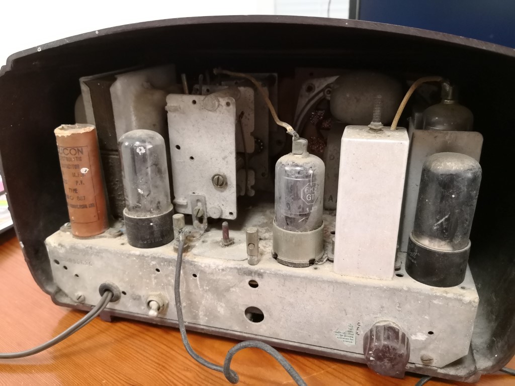
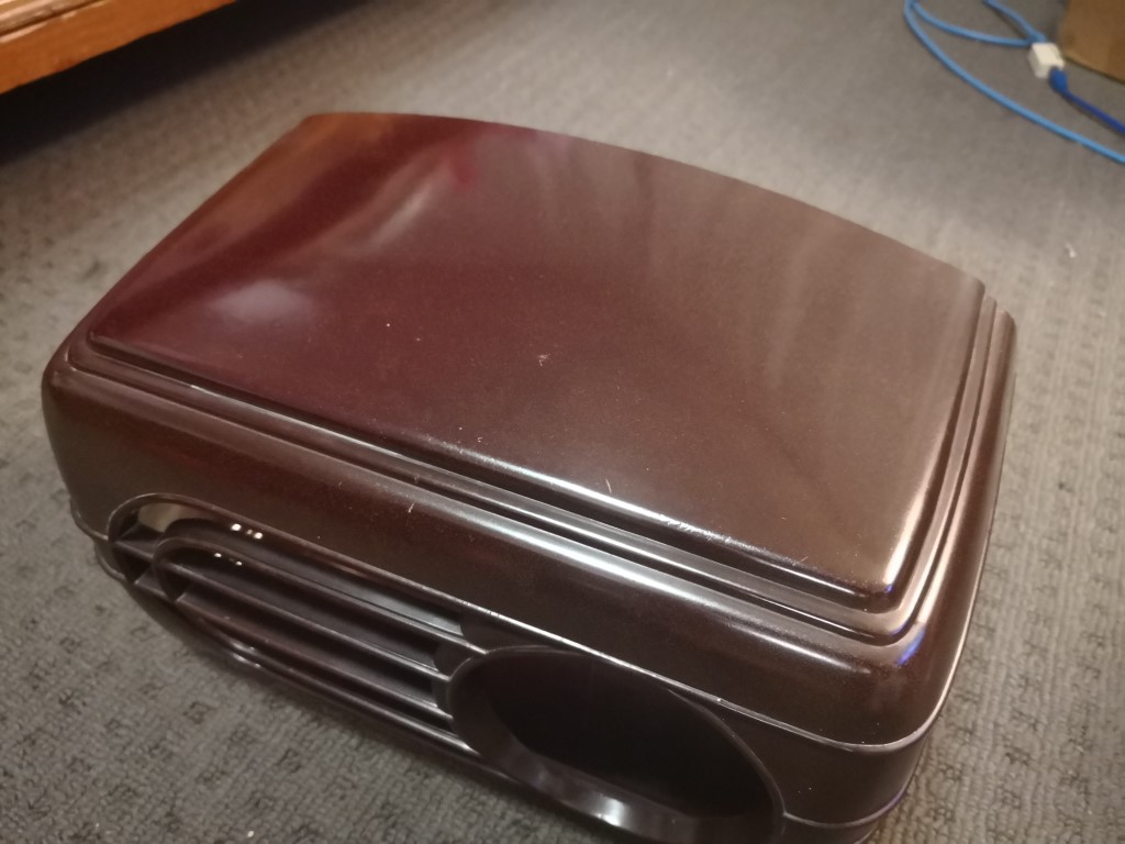
Mechanically, the unit appears to be in quite reasonable condition, with the exception of requiring a pretty decent clean.
The body has no cracks or chips in it, all of the station markers on the dial are intact. The speaker grill cloth is detached slighly in the upper right-hand corner, however this is minor.
I think I should be able to give the case a good scrub and polish it up to have quite a nice finish.
Image Link
Image Link
Image Link
Image Link
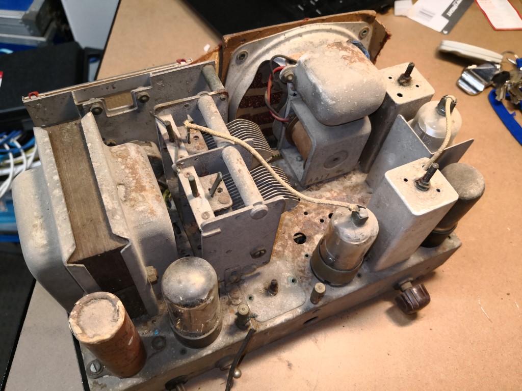
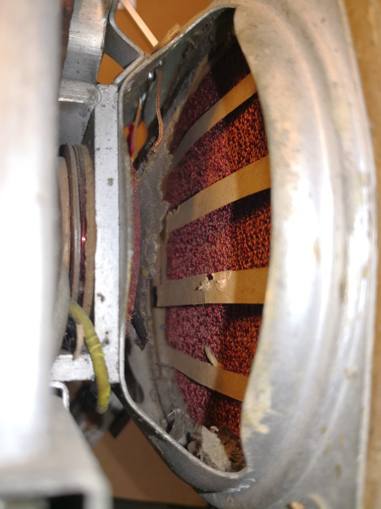
The chassis itself also needs a good clean. The speaker requires a complete replacement as there is around 1 square inch of the cone intact, the rest looks like it was mouse-food. (Given the droppings that came out of it!)
Image Link
Image Link
Image Link
Of the four valves, one is of the wrong type. The 5YG3T, 6V6GT and 6G8G are all correct, however the 6A8G has been replaced with a 6K8GT. I need to determine if this is a suitable replacement or whether I should find the original part.
Image Link
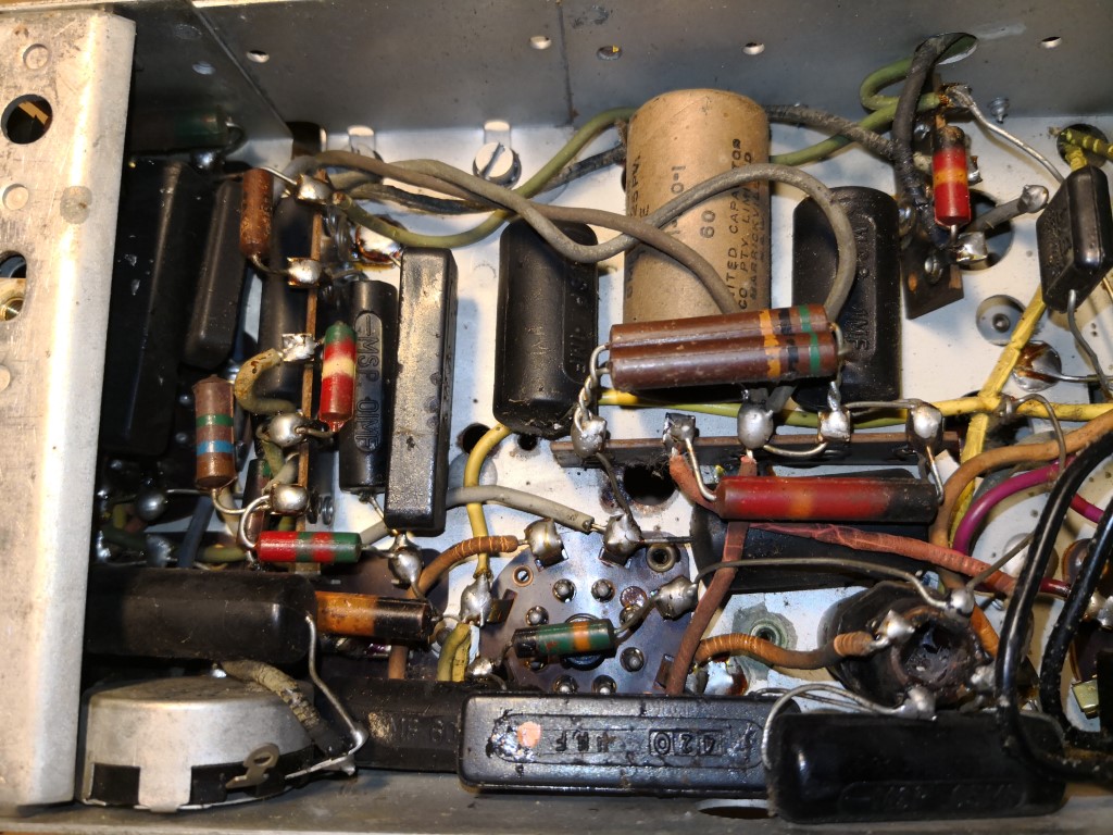
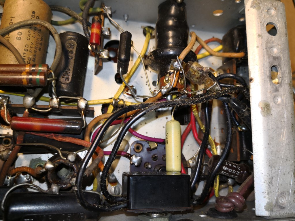
The under-chassis circuitry all looks intact, no major physical problems to note.
Image Link
Image Link
There is alot of Vulcanised Indian Rubber wiring that is falling apart which needs to be replaced.
What sort of wire do you typically replace it with? Obviously the high voltages in-circuit would need to be considered from an insulation perspective.
The two big elecrolyic capacitors will be the first to be replaced.
I note that the bigger one mounted on the chassis has 3 connections at it's base. Based on how it's wired, the inner terminal appears to be the positive, and the two outer tag terminals appear to be the negative.
The transformer center tap goes to one negative terminal, and the two resistors (R12, R13) connect to the other. Is this a standard setup? Would the two terminals be connected internally?
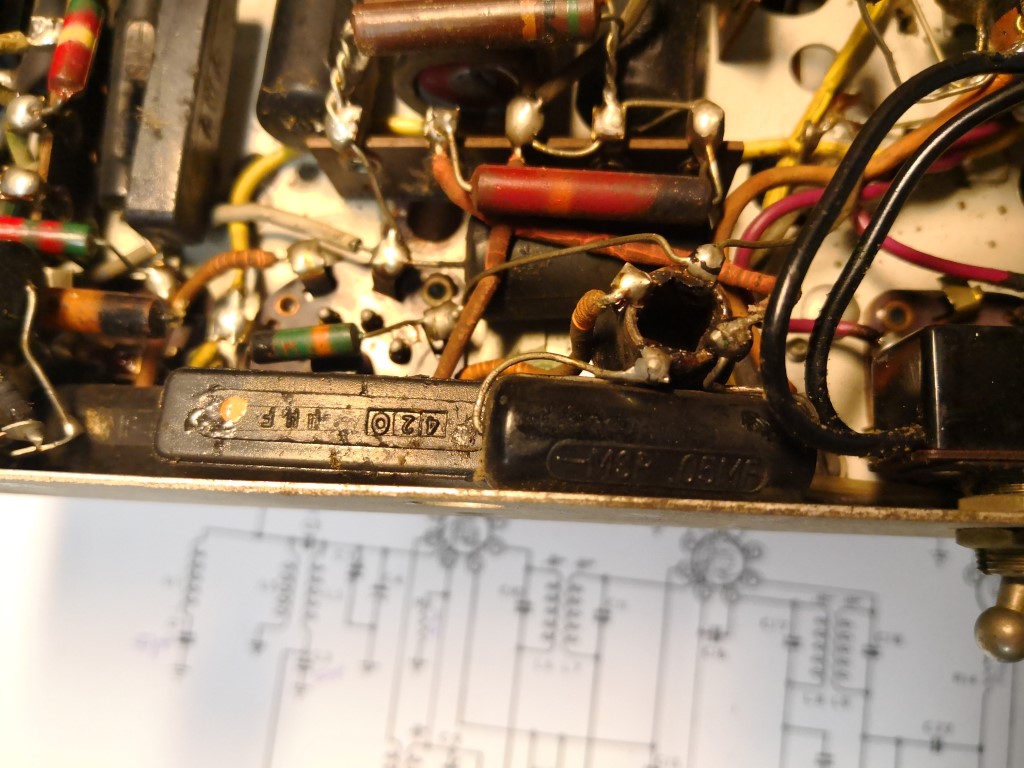
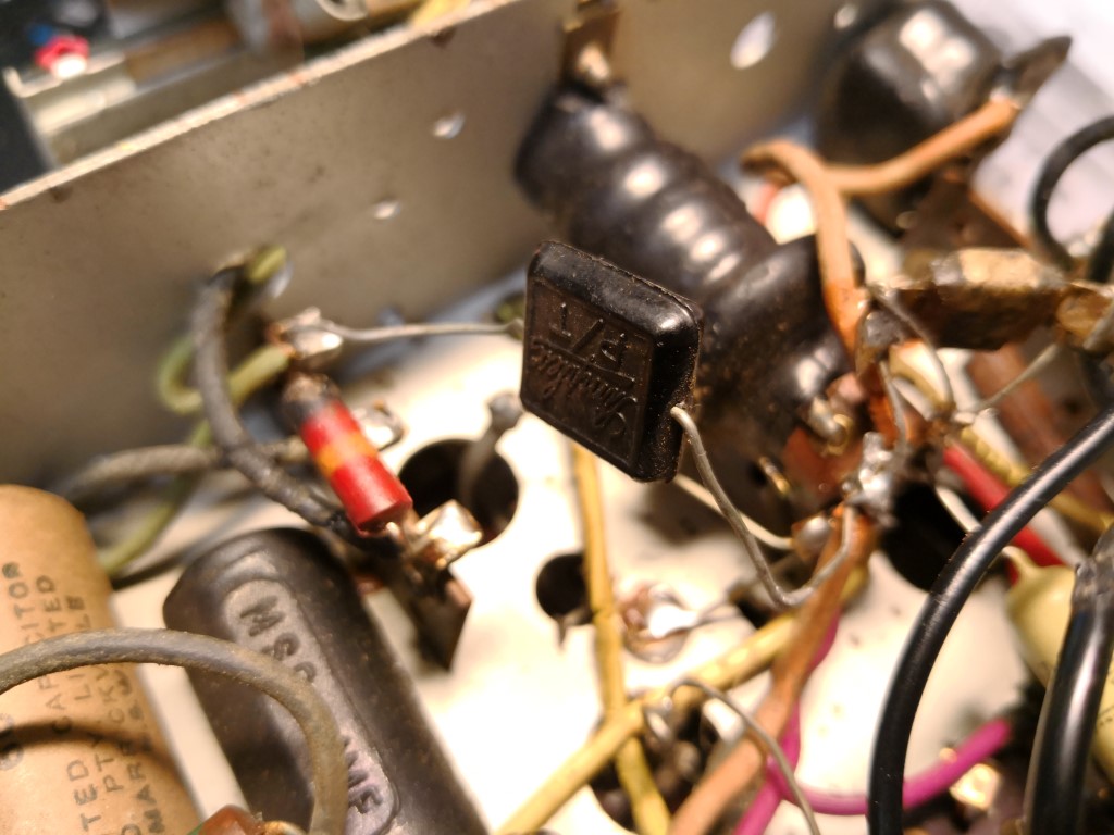
I have read alot about replacing the paper capacitors, however in this unit, all of them appear to be plastic. Even the Mica ones look the same.
For example, the two capacitors pictured below, the left hand square one is a mica type, and the right hand round one is a paper type. Do you think that this is the case here? Or are these replacement capacitors fitted by a 3rd party?
Image Link
That's it for last night's little initial investigation. The only "work" done it so far was to remove the old two-core power lead, eventually a new one will be connected to the switch. This model has a nice double-pole power switch fitted which I'm happy to see.
I'll start probing some of the resistors with a multimeter soon to check they are all within range, and check that none of the valve heater filaments are open circuit.
More updates to come
|
|
|
|
|

|
Location: Belrose, NSW
Member since 31 December 2015
Member #: 1844
Postcount: 2710
|
"The speaker requires a complete replacement as there is around 1 square inch of the cone intact, the rest looks like it was mouse-food. "
That's an electrodynamic speaker and will be hard to replace, You should be able to patch the cone with PVA glue and tissue paper, I have brought much worse than that back into service this way. Watch the glue doesn't run into the voice coil gap.
"Of the four valves, one is of the wrong type. The 5YG3T, 6V6GT and 6G8G are all correct, however the 6A8G has been replaced with a 6K8GT. I need to determine if this is a suitable replacement or whether I should find the original part."
The 6K8GT is a better replacement for the 6A8G (and easier to source). It will be OK.
I"There is alot of Vulcanised Indian Rubber wiring that is falling apart which needs to be replaced.
What sort of wire do you typically replace it with? Obviously the high voltages in-circuit would need to be considered from an insulation perspective."
Try to obtain some heat-proof silicone rubber insulated wire from a large electrical wholesaler, It looks the part and will last forever.
"The two big elecrolyic capacitors will be the first to be replaced."
You won't find chassis mount equivalents, you might have to dig the guts out of the old ones and hide new parts inside them. However, if there's no sign of physical leakage, I'd try the dim bulb technique first. They might re-form successfully and be OK.
"I note that the bigger one mounted on the chassis has 3 connections at it's base. Based on how it's wired, the inner terminal appears to be the positive, and the two outer tag terminals appear to be the negative."
That's correct
"The transformer center tap goes to one negative terminal, and the two resistors (R12, R13) connect to the other. Is this a standard setup?"
Yes, that's your back bias for the output valve.
"Would the two terminals be connected internally?"
Yes
"I have read alot about replacing the paper capacitors, however in this unit, all of them appear to be plastic. Even the Mica ones look the same.
For example, the two capacitors pictured below, the left hand square one is a mica type, and the right hand round one is a paper type. Do you think that this is the case here? Or are these replacement capacitors fitted by a 3rd party?"
Those caps are original AWA parts. The black cylindrical ones are paper and should be replaced. The black rectangular caps are mica and can be left alone, I've never known one of these to be bad..
Sounds like this will be a good resto... Enjoy!
|
|
|
|
|
|
|
Location: Lalor Park, NSW
Member since 7 April 2018
Member #: 2237
Postcount: 57
|
Hi Ian,
Thank you very much for your detailed response and information.
Sounds like I have a bit of work ahead.
Re: The speaker - I have read elsewhere that if I can keep the original field-coil in circuit, I should be able to replace the speaker with a standard permanent magent type?
Obviously i'd need somewhere to mount said coil, but as I understand it, that should electrically work, unless any induced current from the main voice coil is used as part of a feedback circuit, however that doesn't appear to be the case.
Today's job is to build a dim-bulb rig, as well as mounting an RCD on it as well, as my unit is quite old (garage is fused!) and my safety is paramount
|
|
|
|
|

|
Location: Toongabbie, NSW
Member since 19 November 2015
Member #: 1828
Postcount: 1407
|
Having made and repaired radio sets all I can say is "what Ian said"!
That's a nice radio and worth a bit of work.
I would tend to make the set work first of all with replacing as few bits as possible like those horrid black tubular caps and the electros if they don't form up..
That's the "first fix".
That way you can evaluate all the big parts first of all and see if there are any disasters like open circuit windings in coils.
The you can decide on a "second fix" level, that is strip it completely down to the bare metal, or do nothing, or something in between like replace the worst wiring and parts.
Have a look at some of my antics in special projects.
Ian is correct with the speaker, it just needs a new cone made up from paper or some sort and glued up to suit like making a model airplane with doped tissue paper. The speaker is 90% there, its just the cone is missing. I have recreated fragile cones by doping the fragile bits together. Size up a stock cheap speaker the cone on a cheepy may make up 90% of what you want. Alternatively use a permag and add a choke or a dropping resistor. Have a go at fixing the original you cant make it worse!
Cheers, Fred.
|
|
|
|
|

|
Location: Wangaratta, VIC
Member since 21 February 2009
Member #: 438
Postcount: 5715
|
Note that all of the capacitors on the parts list marked "paper" will have to go, Mice love them but that is not the reason to replace: Rarely is one in several hundred still good. It also pays to check the resistors The grid resistors on 6V6 and often the plate resistors on valves like 6B6 have high attrition rate. Whist not all resistors can be accurately checked "In circuit" if its high (normal fail) it's likely a dud. I commercially fix so if its more than 10% its liable to get replaced.
Polishing Bakelite is a risky business. Car polish containing Sodium Bi Carbonate as the abrasive can leave the BiCarb as a white powder in the pores & if there is Silicone its nigh impossible to get out. The shiny layer on Bakelite is thin big job restoring the shine if you remove it.
Often where a cabinet can be totally stripped you can wash it alkali can damage the Bakelite so be careful: Even Soda Ash will damage. Often brown Bakelite comes up well with a wipe of Linseed oil. It also kills borers in wooden cabinets.
With the normal warning re modern caps I would not use less than 500V caps. They are quoting the normal 525 Surge Volts (Modern caps don't do that); prefer 600V
|
|
|
|
|
|
|
Location: Lalor Park, NSW
Member since 7 April 2018
Member #: 2237
Postcount: 57
|
Good evening radio folk! Hope you all had a nice relaxing ANZAC day, not forgetting the hard work our diggers have done for us.
So here's the next progress update on my 517M restoration project.
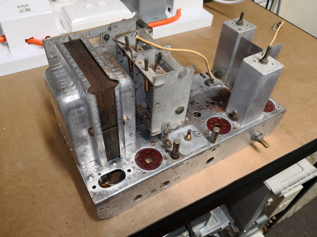
I've stripped out the valves, speaker and the electrolytic cap from the top of the chassis. Also the tuning capacitor and power transformer were temporarily removed.
Gave it a really good scrub up, cleaned most of it up and tried to get it a little polished.
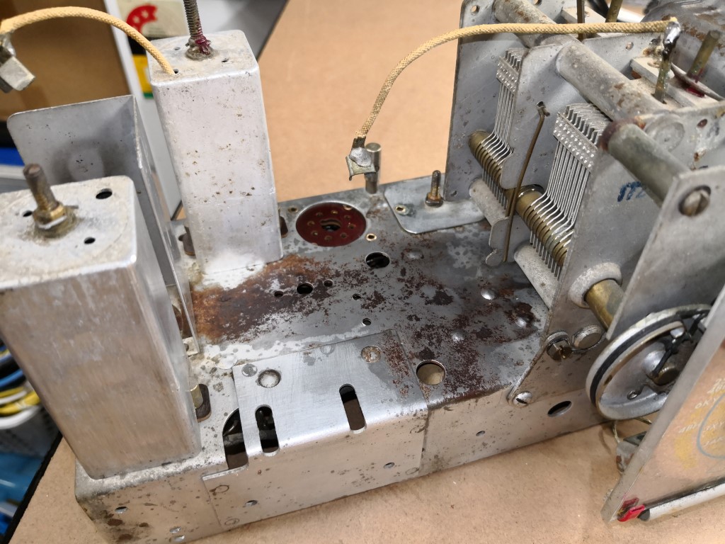
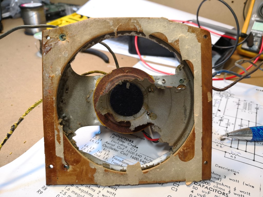
There's a fair amount of deep rust as can be seen where the speaker was; I've tried hitting this with some CLR which has removed most of it, however it's still a bit mucky.
I'm not too fussed however, because once the chassis is mounted back in the shell, it'll be relatively invisible
Image Link
Image Link
As mentioned before, the speaker has a fair bit of damage to it. I'm still deciding the best way to approach this. The good thing is that all three speaker coils are reading the correct resitances. So it should be operational.
Image Link
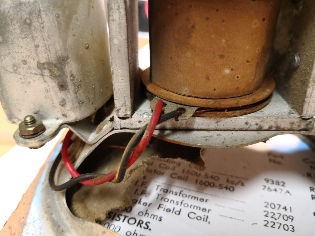
One thing I noticed, is that there is another coil in series with the voice coil of the speaker, and connected to the secondary of the output transformer.
This seems to be wrapped alongside the field coil; however electrically separate. What would this be used for? Is it some form of dapenening for the speaker?
Image Link
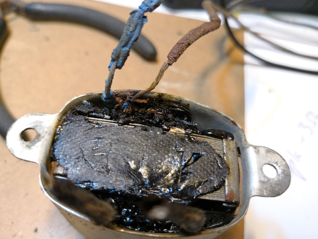
The output transformer has some wiring with perished insulation on the primary side. I'm thinking of cutting the wire about an inch from the transformer body, soldering on some new wire and heatshrinking it.
I'm assuming that the black sticky stuff is some older version of resin potting. I'm hoping with some heat I can loosen up the wiring a bit more to have better insulation.
Image Link
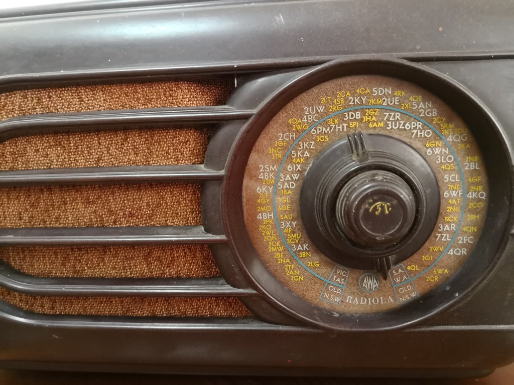
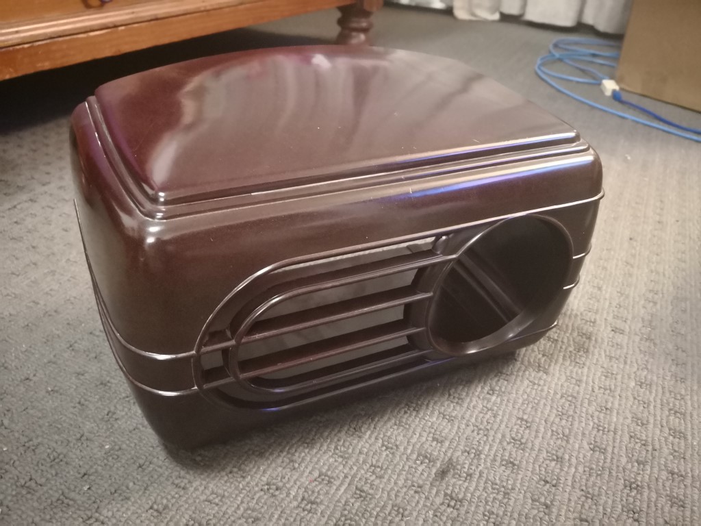
The shell has been given a good clean and scrub with brasso. I'm very impressed the way the bakelite has come up. It looks like a million bucks now and I'm quite happy with the result.
Image Link
Image Link
Electrically, I've noticed some interesting bits when comparing the circuit diagram to the actual ciruitry.
Some of them appears to be factory changes, and there appears to be one capacitor replaced by someone previously.
The replacement cap is yellow and has an E12 value (47nF) whereas everything original are AWA black caps and this one C3 is 50nF.
A check of most of resistors in-circuit is showing they are pretty much on-par. What's the standard tolerance I should be aiming for? 10%?
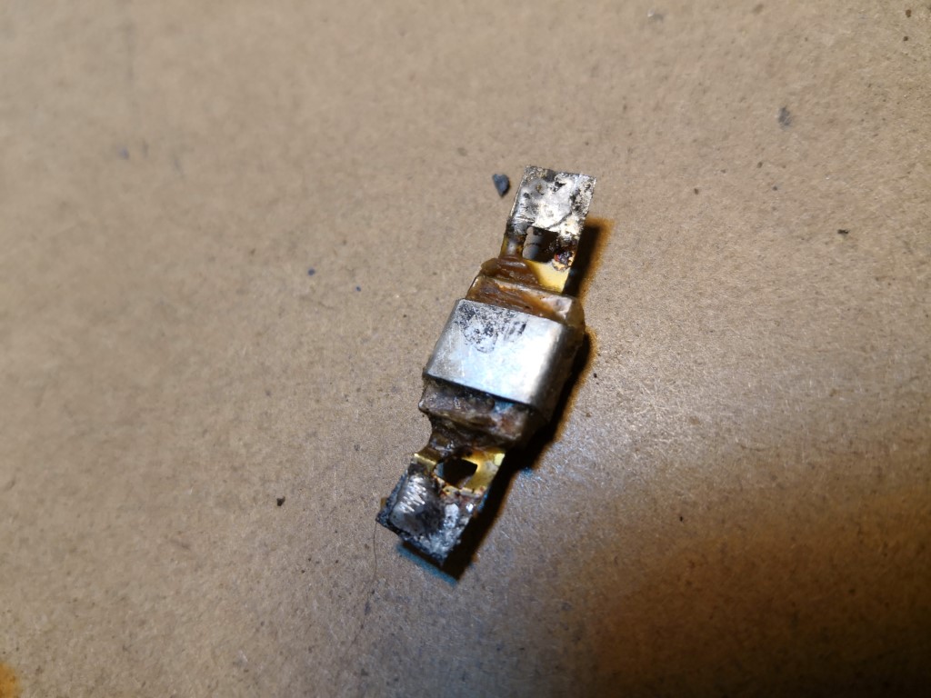
There is something which I believe (based on its connection) is C2, connecting across the RF coils L2 and L3.
I can't seem to see any markings on it, so I'm just making a guess that it's a capacitor and that it's 4pF. This had a wire link soldered across it, shorting it out. Can anyone identify this device?
Image Link
The entire tone control doesn't appear on the circuit diagram either. This is a variable resistor and capacitor in series, connecting between the plate of the 6V6GT and ground.
It makes a bit of sense for something like this to exist here, although I would have expected it to be before the amplification stage.
Another mica capacitor and resistor connect from the plate of the 6G8G through to ground. (That's off memory, I dont have my annotated circuit diagram on me). This appears to be original because it's a black mica AWA branded cap that matches the rest, and the resistor has the old style colour markings.
There's also a random capacitor (I think - it's the black square thing in the next photo) which connects from essentially the aerial socket (L1 / L2 / C2 connection) through to between R8 and the wiper of the volume pot, R9.
I'm not sure what purpose this would serve.
Image Link
Also in far right of the above photo, you can see that capacitor I mentioned above, connected to the coil. Yeah, out of focus As well, you can see the link shorting it out - the V shaped wire between the terminals onto the coil.
To come:
- I've ordered a bunch of capacitors to start replacing all of the paper and electrolytic ones. Was hoping they'd be here by the weekend but no such luck. So re-capping will occur once it's all arrived.
- I will need to order some replacement speaker grille cloth. Any ideas on suppliers of the older looking stuff?
- The knobs need cleaning and polishing. I have managed to get the tone and volume knobs off by loosening their grub screw. The tuning knob looks like it's missing it's screw! But it's on quite tight. I might polish it in place, very carefully.
- The speaker needs reconing. This, I think, is going to be the hardest job of this restore.
- There are a few wires that need replacing as the insulation barely exists. The dial lamp wiring, the B- common wire from the transformer, the output transformer wiring as mentioned above, the volume control wires.
- Re-assembling electrically and physically, testing all the circuits, and realigning the receiver.
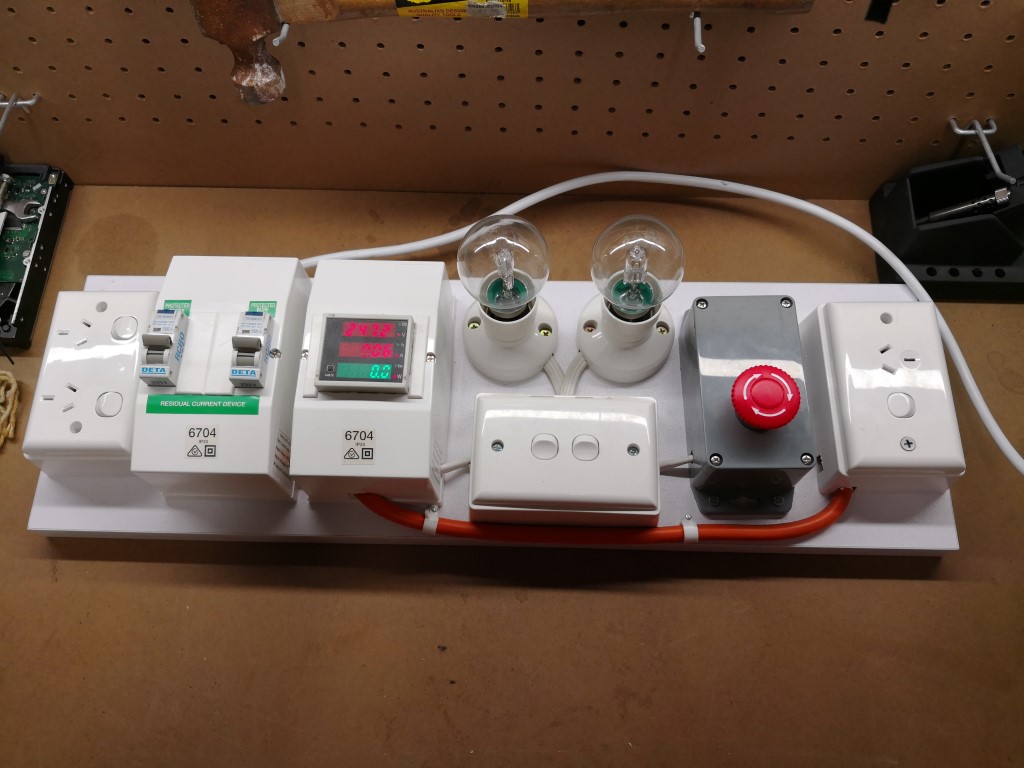
I've also had a bit of fun making this little test-bed. Being in an old unit block, my garage still has the 1970s dinosaur fuse protecting it. RCDs are non-existant. So this was made to save me, as well as provide some testing features .
Image Link
It contains from left to right-
- Double GPO, for tools etc
- Two RCDs, one controlling the DGPO, and one controlling the test GPO
- Electrical meter showing voltage delivered to, and current drawn by the test GPO. It can also show kWh, Total Time, and cosθ with a touch of a button
- Two lamps that can be switched in series with test load, or bypassed.
- Emergency stop button & 3A breaker (not visible).
- Test outlet
Till next time - thanks for listening!
Mike
|
|
|
|
|

|
Location: Sydney, NSW
Member since 28 January 2011
Member #: 823
Postcount: 6949
|
there is another coil in series with the voice coil of the speaker
Probably a filter choke -- part of the B+ DC filter.
I'm assuming that the black sticky stuff is some older version of resin potting
It's tar.
What's the standard tolerance I should be aiming for? 10%?
10% is usual.
Can anyone identify this device?
Looks like a cap, though odd to be shorted out.
I've also had a bit of fun making this little test-bed.
Nice job.
|
|
|
|
|
|
|
Location: Belrose, NSW
Member since 31 December 2015
Member #: 1844
Postcount: 2710
|
There is another coil in series with the voice coil of the speaker
Probably a filter choke -- part of the B+ DC filter.
It's called a hum bucking coil. Common in ED speakers, "bucks" the ripple in the magnetic field.
I'm assuming that the black sticky stuff is some older version of resin potting
It's tar.
What's the standard tolerance I should be aiming for? 10%?
10% is usual. Unless there's a silver band or end, 20% used to be more common.
Can anyone identify this device?
Looks like a cap, though odd to be shorted out. It's a mica cap....
I've also had a bit of fun making this little test-bed.
Nice job. Agreed!!
|
|
|
|
|
|
|
Location: Lalor Park, NSW
Member since 7 April 2018
Member #: 2237
Postcount: 57
|
Thanks GTC and Ian for your answers! Always appreciated
|
|
|
|
|

|
Location: Brighton Le Sands, NSW
Member since 18 January 2016
Member #: 1860
Postcount: 9
|
Hi Mike
The AWA 517 was like most of AWA’s Bakelite radios of that immediate period was available in 7 colour. Over the years I have owned all 7 colours in this model which were brown ( advertised as walnut ) burgundy, white ( advertised as ivory ) butterscotch ( advertised as mahogany ) turquoise ( advertised as eau-de-nil ), green ( advertised as both green & jade ) & marbleised ( advertised as grained ivory or marbled ivory ).
Your example here is not Brown it is actually burgundy & if you saw it compared to a brown the pair would look completely different.
From the pictures your radio is also missing the AWA RADIOLA clear plastic badge which sits in the centre of the tuning knob. If you would like to buy one of these for your restoration I can supply one at a cost of $20 posted. Fell free to call me on 0413282083.
Kind Regards
Scott.
|
|
|
|
|
|
|
Location: Lalor Park, NSW
Member since 7 April 2018
Member #: 2237
Postcount: 57
|
So last night I finished off the recapping and rewiring of the perished cables.
Wired the chewed up speaker back in as well.
Started the chassis up with the dim bulb, no valves, all the transformer voltages came out good.
Plugged in the valves, and measured some other voltages. All the plate and screen voltages, as well as B+ were within 5V of the stated voltage on the guide. Looking good so far!
Turned up the volume and cycled the tuner, and got some crackles and noises. Eventually managed to get sound of out of it by putting the speaker with the (partial) cone facing upwards. Very happy at this point.
Attached my signal gen and CRO and started the alignment - all seemed to go quite well.
Put on a short (1M) antenna wire, and lo-and-behold, alot of Sydney stations were coming through. 2BL, 2GB, 2UE and 2CH were easy to find.
The sound out of the crap speaker was buzzy, but this was not mains hum, just noise from the bad cone when the lower bass notes in some of the voice and music hit as the edges vibrated around.
So for a first vintage electrical restore, I'm already very impressed with how it's come out so far.
To do from here is:
1. Rebuild/recone speaker
2. Clean dial face
3. Attach permanent (safe) power cable
4. Reassemble radio
5. Enjoy!
|
|
|
|
|
|
|
Location: Sydney, NSW
Member since 28 January 2011
Member #: 823
Postcount: 6949
|
So for a first vintage electrical restore, I'm already very impressed with how it's come out so far.
As am I. Well done!
|
|
|
|
|
|
|
Location: Lalor Park, NSW
Member since 7 April 2018
Member #: 2237
Postcount: 57
|
Thanks GTC
It's a nice feeling bringing something twice my age back to life!
|
|
|
|
|

|
Location: Latham, ACT
Member since 21 February 2015
Member #: 1705
Postcount: 2228
|
In my case GTC it would only be 42 years old lol.
|
|
|
|
|
|
|
Location: Latham, ACT
Member since 21 February 2015
Member #: 1705
Postcount: 2228
|
As far as speaker cloth for AWAs try John McIlwaine from the Sydney HRSA his email is on the HRSA website he is a top bloke.
|
|
|
|
|
|
You need to be a member to post comments on this forum.
|
