Welcome to Australia's only Vintage Radio and Television discussion forums. You are not logged in. Please log in below, apply for an account or retrieve your password.
Australian Vintage Radio Forums
  Home  ·  About Us  ·  Discussion Forums  ·  Glossary  ·  Outside Links  ·  Policies  ·  Services Directory  ·  Safety Warnings  ·  Tutorials

Tech Talk

Forum home - Go back to Tech talk

 Restoring an AWA Radiola 517M
« Back · 1 · 2 · Next »
 Return to top of page · Post #: 16 · Written at 11:53:49 PM on 5 June 2018.
Skymaster's Gravatar
 Location: Lalor Park, NSW
 Member since 7 April 2018
 Member #: 2237
 Postcount: 57

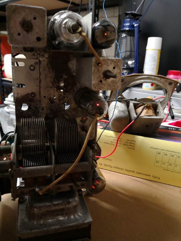
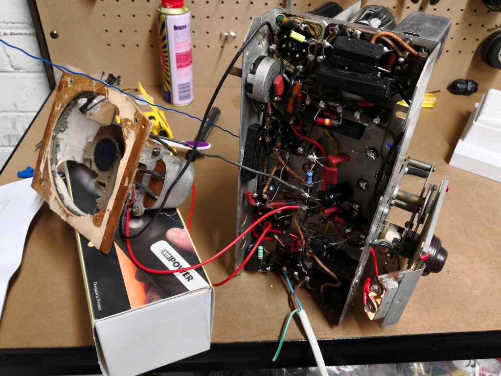
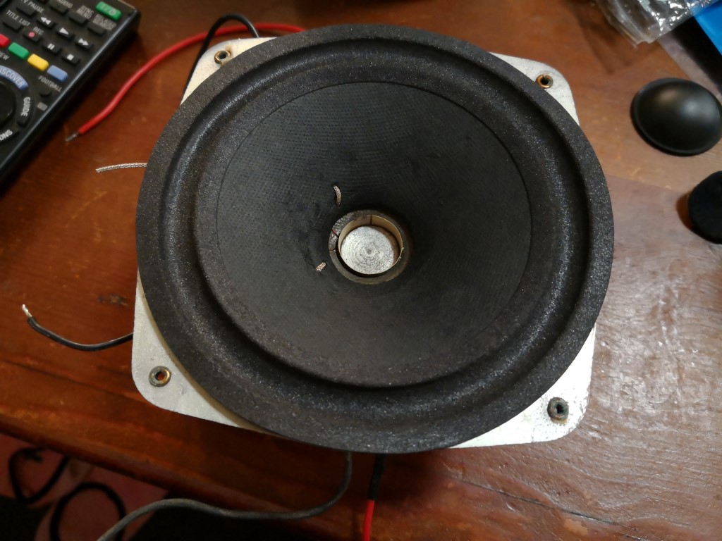
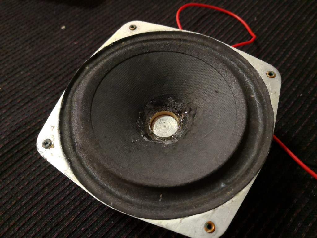
Ok, so I missed pictures last time, so here are some of the first power up.
As you can see, the valves are glowing nicely.
Image Link

I had it propped up on the bench like this to allow me to solder in the speaker wires as they go to various parts of the circuit, and length wouldnt allow me to sit it up properly.
Image Link

Yes, I'm aware of how the 'temporary' power cord is attached. This is going back to the dim-bulb RCD test board mentioned above.

And, for good measure - here's a video I made of the speaker playing out. Yes, it's crackly as all hell, but that's because the bits of paper cone are flapping all over the place. And yes, it's shot on my mobile, so it does some funky stuff as I move the phone around. But the clarity of the reception and the amplification I am quite impressed with.

https://youtu.be/p4r1xIw7FN0
(you might need to copy and paste this in - not sure how to link here!)

So after waiting a good bit of time for some parts to arrive, I received the new cone for the speaker.
Image Link
6 bucks delivered from China. Not bad at all.

First things first, I pulled off the old felt dust-cap, revealing the voice coil underneath.
Image Link

The spider has a small amount of damage to it, but the effort of ripping it all apart is not worth it, and it is holding the coil in position nicely.

Next up is doing a test fit. Felt a little big to begin with, however as you can see further down below, once in place, it's quite snug and perfect.
Image Link

The new cone has a slightly taller angle than the old one. But that's OK, I detached the old cone from the surround, it was only there to support the coil wires.
Image Link

A mock-up with the new dustcap (I won't use it, I prefer the look of the original felt one) and the original paper gasket sitting around the rim.
The new cone sits proud of the basket, but I'm not too fussed about that - if I remember correctly there is enough clearance for it in the case.
Image Link

To mount the speaker, I detached the original cone from the basket, but left the section where the voice coil wires attached, with around 5mm of paper above these wires.
At this point, some decent craft glue was run around the outside rim of the new cone, and it seated and positioned directly on top of the old cone. A second run of glue was used to fill the gap between the voice coil and the new cone.
Once this had hardened after about 10 minutes, a small bead of glue was run around the outside of the basket rim, and the original gasket was used to press the outer edge of the rubber suspension into place.
Image Link

After another 10 minutes of hardening, some glue was placed between the old cone and the new one, on the last remaining part. This was jimmied in with a cable tie. I managed to get my fingers in behind to give it a squeeze and seal the two parts together.
Image Link

This has now been left for the glue to cure. The next step will be refitting the speaker to the chassis, wiring it back in, and giving it a test run!


 Return to top of page · Post #: 17 · Written at 6:52:12 AM on 6 June 2018.
Fred Lever's Gravatar
 Location: Toongabbie, NSW
 Member since 19 November 2015
 Member #: 1828
 Postcount: 1250

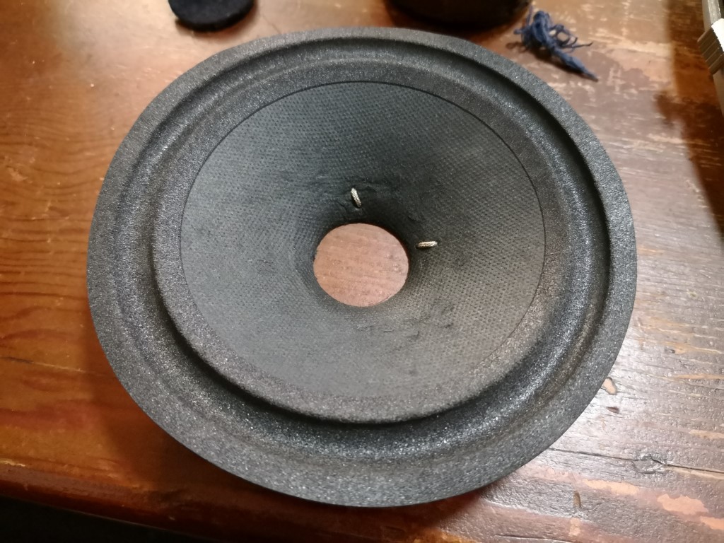
O, well done with the speaker!
That's exactly how to do it.
Too many people fuss and carry on about repairing stuff, but a thing like the speaker is just another mechanical thing to me.
You have simply replaced the bit that was missing.
With house radios we are not repairing a Wharfdale or some exotic thing for golden ears.
So long as the coil doesn't scrape and nothing flaps its all good.
Keep going.
Fred.


 Return to top of page · Post #: 18 · Written at 9:03:31 AM on 6 June 2018.
Skymaster's Gravatar
 Location: Lalor Park, NSW
 Member since 7 April 2018
 Member #: 2237
 Postcount: 57

Thanks Fred!

That mirrors my thoughts exactly. I was trying to keep it as simple as possible, without ripping the entire unit apart. It's not like we are reproducing every conceivable range of frequencies at completely flat level. If only we were so lucky with AM Smile

The coil seems to be held rightly in position by the spider, and a quick check this morning of working the cone by hand seems like everything is all good. No scrapes, at least 3-4mm of coil movement, so I'm quite hopeful.

Tonight's job will be to wire it back in and see how it plays.


 Return to top of page · Post #: 19 · Written at 6:30:16 PM on 6 June 2018.
Skymaster's Gravatar
 Location: Lalor Park, NSW
 Member since 7 April 2018
 Member #: 2237
 Postcount: 57

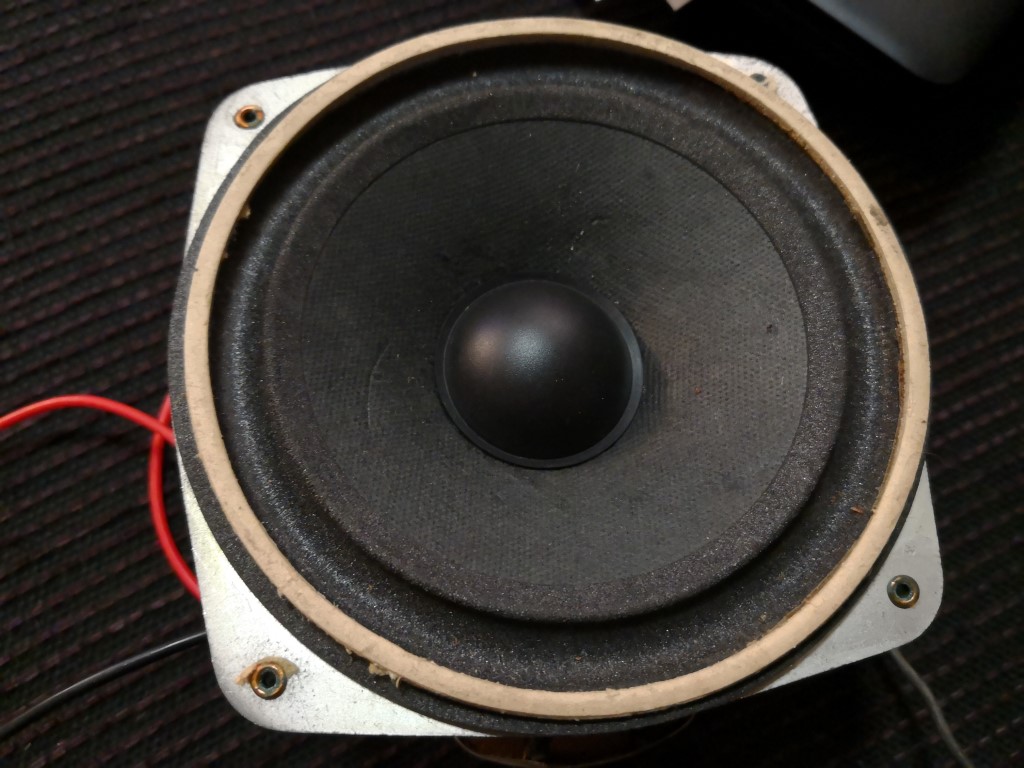
So I got the speaker fitted to the chassis and it sounds awesome. Very happy with the result.

Video here: https://youtu.be/w1SjiojLe_E

Was shot with a mobile so it's not perfect reproduction, alot of the bottom end is missing in the recorded video.


 Return to top of page · Post #: 20 · Written at 7:07:00 AM on 8 June 2018.
Tallar Carl's avatar
 Location: Latham, ACT
 Member since 21 February 2015
 Member #: 1705
 Postcount: 2156

That's one awesome repair job. I will be starting one this coming weekend . Getting a radio repaired for a buddy.


 Return to top of page · Post #: 21 · Written at 9:57:52 AM on 8 June 2018.
Marcc's avatar
 Location: Wangaratta, VIC
 Member since 21 February 2009
 Member #: 438
 Postcount: 5256

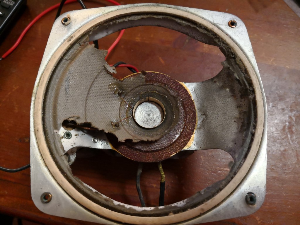
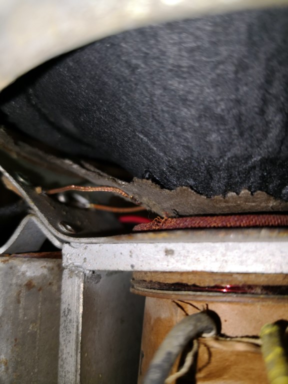
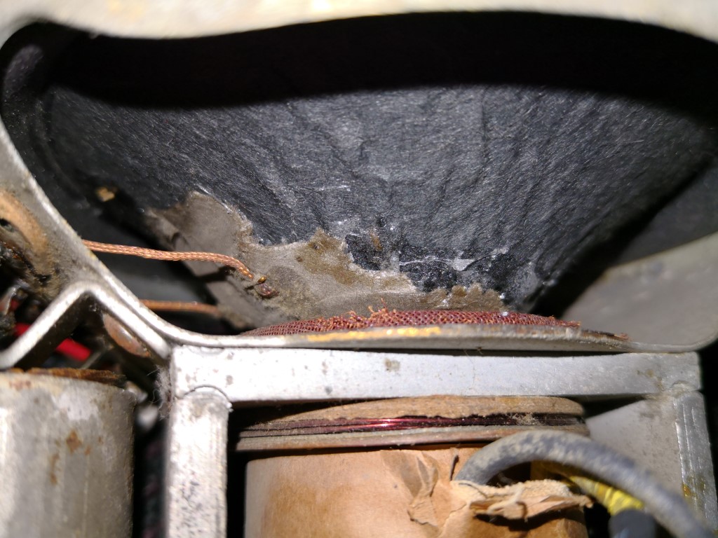
What you can do with a stuffed, cone Electrodynamic speaker is disconnect the Voice coil & patch to a permanent magnet speaker.

Apart from sensitivity, the main reason I have a CRO synchronised with the Signal generator, is that it can show distortion and then be the signal tracer to find the source.

If you need to sub to a Permag speaker, advise for method.

Marc


 Return to top of page · Post #: 22 · Written at 6:46:51 PM on 27 June 2018.
Skymaster's Gravatar
 Location: Lalor Park, NSW
 Member since 7 April 2018
 Member #: 2237
 Postcount: 57

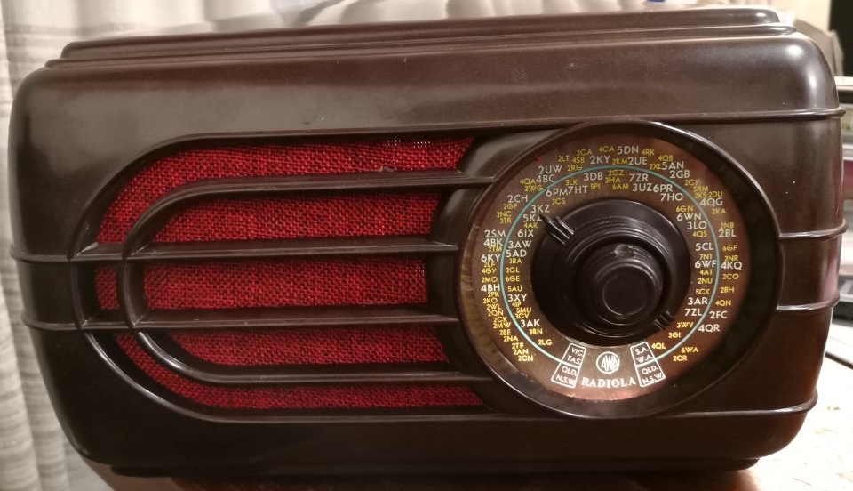
I managed to find some 'Burgundy Burlap' fabric, which looks the part replacing the original ripped & faded grill cloth.

Because the new speaker cone is now sitting proud of the basket, I wasnt able to attach the cloth as it was originally.
With a bit of craft glue, it's now stuck to the inside of the enclosure, doubled over to give it a bit more depth to it.

Image Link

And so now I'm finally done!
I'm very happy with the outcome, and for a first vintage restore; I've certainly learnt alot.

I think there will need to be more restorations to come Smile

Thanks for listening!

Mike


 Return to top of page · Post #: 23 · Written at 9:00:29 PM on 27 June 2018.
Marcc's avatar
 Location: Wangaratta, VIC
 Member since 21 February 2009
 Member #: 438
 Postcount: 5256

Some speakers had a thick gasket on the rim of the cone & that allowed forward excursions of the cone. One of the tricks with a lot of fabric is to make a "Stretcher" from heavy cardboard & mount the cloth on it first.

Marc


« Back · 1 · 2 · Next »
 You need to be a member to post comments on this forum.

Sign In

Username:
Password:
 Keep me logged in.
Do not tick box on a computer with public access.