
Tech Talk
Forum home - Go back to Tech talk
|
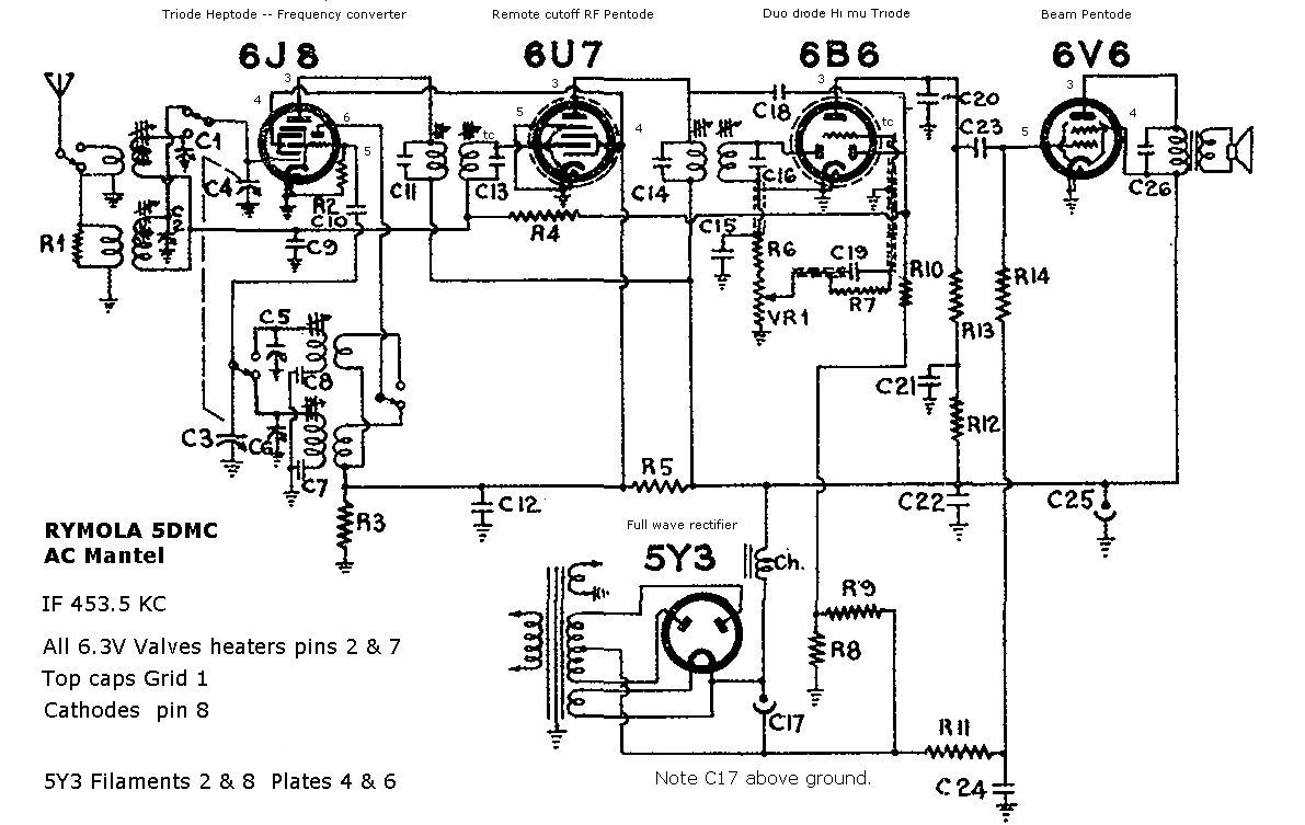
6V6GT issue - Rymola254-81?
|
|
|
Return to top of page · Post #: 1 · Written at 11:57:06 PM on 7 August 2009.
|
|
|
|
Location: Riddells Creek, VIC
Member since 7 August 2009 Member #: 526 Postcount: 123 |
|
Have a chassis out of a Rymola 254-81 which I beleive may have been used in other brands as well? Info for this brand is very scarce. In fact any info at all is welcomed greatly!! |
|
|
Return to top of page · Post #: 2 · Written at 1:08:19 AM on 9 August 2009.
|
|

|
Location: Wangaratta, VIC
Member since 21 February 2009 Member #: 438 Postcount: 5715 |
|
Circuit does not mention value. If you have the original it may be on it? |
|
|
Return to top of page · Post #: 3 · Written at 10:26:42 PM on 9 August 2009.
|
|
|
|
Location: Riddells Creek, VIC
Member since 7 August 2009 Member #: 526 Postcount: 123 |
|
G'day Marc & thanks for the Response |
|
|
Return to top of page · Post #: 4 · Written at 12:54:45 AM on 10 August 2009.
|
|
|
|
Location: Wangaratta, VIC
Member since 21 February 2009 Member #: 438 Postcount: 5715 |
|
It would appear that something is very wrong in the wiring of the 6V6 and one needs to get a copy of a 6v6 circuit or that radio's and become au fait with it and the basics of how it all works. |
|
|
Return to top of page · Post #: 5 · Written at 11:19:51 PM on 10 August 2009.
|
|
|
|
Location: Riddells Creek, VIC
Member since 7 August 2009 Member #: 526 Postcount: 123 |
|
Thanks Marc, will try find Brads email on here some where, in the meantime I will also draw out the CCT diagram as it stands now to accompany the PIC. No mods appear to have been made to the unit -other than removal from its original console! (shame) ;( |
|
|
Return to top of page · Post #: 6 · Written at 10:08:54 PM on 11 August 2009.
|
|
|
|
Location: Wangaratta, VIC
Member since 21 February 2009 Member #: 438 Postcount: 5715 |
|
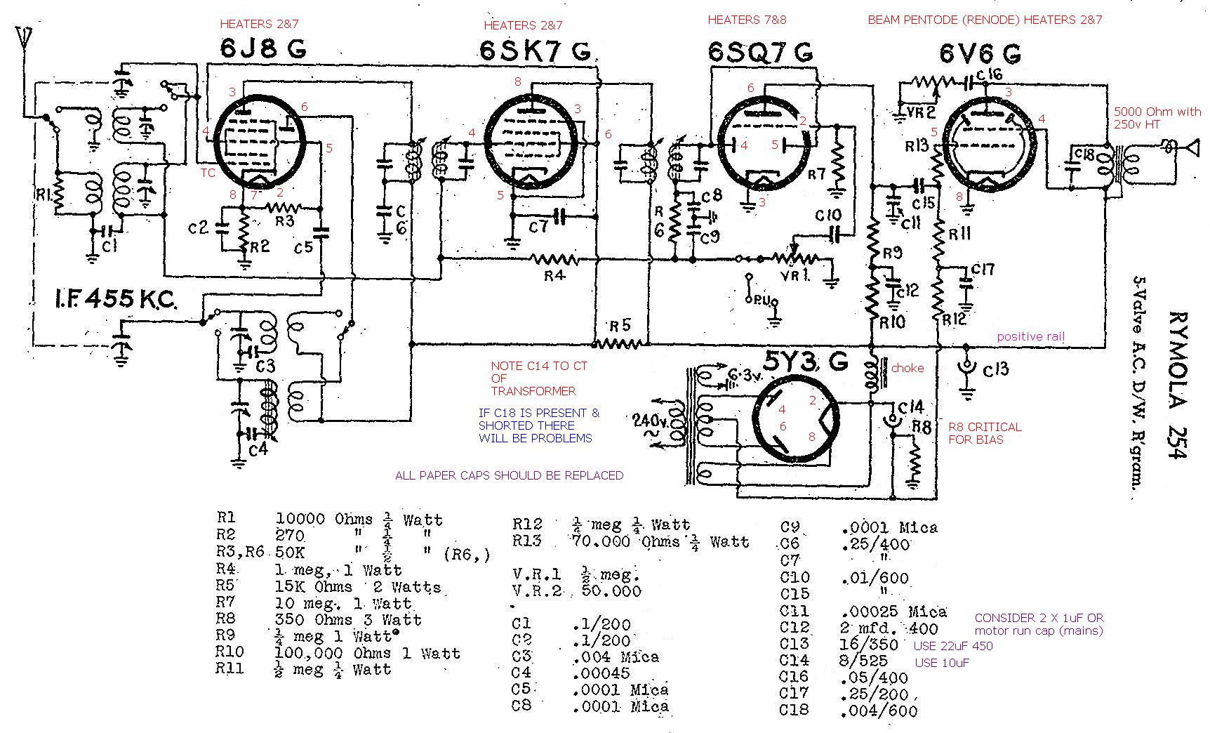
I have forwarded a copy of a circuit, to which I have added pin numbers, to Brad and asked him to send it to you. |
|
|
Return to top of page · Post #: 7 · Written at 11:16:03 PM on 11 August 2009.
|
|

|
Administrator
Location: Naremburn, NSW
Member since 15 November 2005 Member #: 1 Postcount: 7624 |
|
Brad ‾‾‾‾‾‾‾‾‾‾‾‾‾‾‾‾‾‾‾‾‾‾‾‾‾‾‾‾‾‾‾‾‾‾‾‾‾‾‾‾‾‾‾‾‾‾‾‾‾‾‾‾‾‾‾‾‾‾‾‾‾‾‾‾‾‾‾‾ A valve a day keeps the transistor away... |
|
|
Return to top of page · Post #: 8 · Written at 10:35:22 PM on 12 August 2009.
|
|
|
|
Location: Riddells Creek, VIC
Member since 7 August 2009 Member #: 526 Postcount: 123 |
|
Tar, look forward to receiving it, have sent pics of unit to Brad to forward/post.  |
|
|
Return to top of page · Post #: 9 · Written at 7:33:16 PM on 14 August 2009.
|
|
|
|
Administrator
Location: Naremburn, NSW
Member since 15 November 2005 Member #: 1 Postcount: 7624 |
|
They've arrived safely. I'll post them tomorrow morning. ‾‾‾‾‾‾‾‾‾‾‾‾‾‾‾‾‾‾‾‾‾‾‾‾‾‾‾‾‾‾‾‾‾‾‾‾‾‾‾‾‾‾‾‾‾‾‾‾‾‾‾‾‾‾‾‾‾‾‾‾‾‾‾‾‾‾‾‾ A valve a day keeps the transistor away... |
|
|
Return to top of page · Post #: 10 · Written at 8:47:01 PM on 15 August 2009.
|
|
|
|
Location: Wangaratta, VIC
Member since 21 February 2009 Member #: 438 Postcount: 5715 |
|
OK ..... Brad has kindly forwarded the pictures to me and others will look forward to seeing where I am about to go. 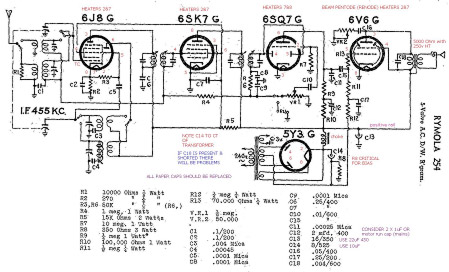 |
|
|
Return to top of page · Post #: 11 · Written at 1:08:34 PM on 16 August 2009.
|
|
|
|
Administrator
Location: Naremburn, NSW
Member since 15 November 2005 Member #: 1 Postcount: 7624 |
|
I almost forgot, the following link leads to a full size image of the circuit diagram. ‾‾‾‾‾‾‾‾‾‾‾‾‾‾‾‾‾‾‾‾‾‾‾‾‾‾‾‾‾‾‾‾‾‾‾‾‾‾‾‾‾‾‾‾‾‾‾‾‾‾‾‾‾‾‾‾‾‾‾‾‾‾‾‾‾‾‾‾ A valve a day keeps the transistor away... |
|
|
Return to top of page · Post #: 12 · Written at 8:13:40 PM on 16 August 2009.
|
|
|
|
Location: Wangaratta, VIC
Member since 21 February 2009 Member #: 438 Postcount: 5715 |
|
Note previous post unsoldered (typo) |
|
|
Return to top of page · Post #: 13 · Written at 9:49:36 PM on 16 August 2009.
|
|
|
|
Administrator
Location: Naremburn, NSW
Member since 15 November 2005 Member #: 1 Postcount: 7624 |
|
No worries there Marc. I'll sort this out tomorrow night when I have access to the database again. ‾‾‾‾‾‾‾‾‾‾‾‾‾‾‾‾‾‾‾‾‾‾‾‾‾‾‾‾‾‾‾‾‾‾‾‾‾‾‾‾‾‾‾‾‾‾‾‾‾‾‾‾‾‾‾‾‾‾‾‾‾‾‾‾‾‾‾‾ A valve a day keeps the transistor away... |
|
|
Return to top of page · Post #: 14 · Written at 3:07:00 PM on 17 August 2009.
|
|
|
|
Location: Wangaratta, VIC
Member since 21 February 2009 Member #: 438 Postcount: 5715 |
|
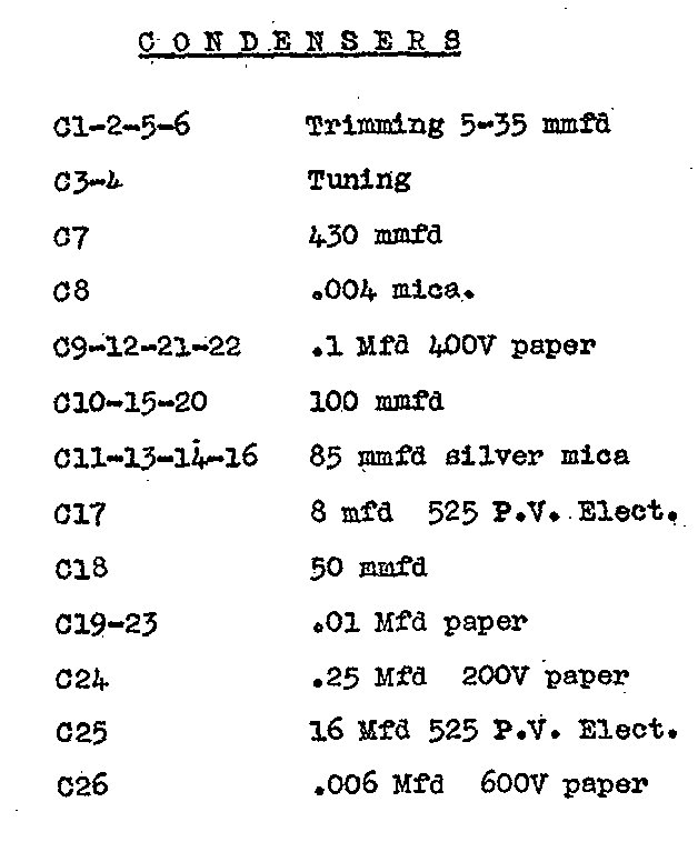
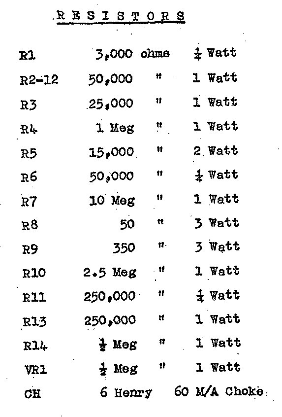
New paperwork issued. |
|
|
Return to top of page · Post #: 15 · Written at 6:28:02 AM on 18 August 2009.
|
|
|
|
Administrator
Location: Naremburn, NSW
Member since 15 November 2005 Member #: 1 Postcount: 7624 |
|
G'day Marc, I've forwarded that e-mail as requested. Below are the links to the three images: ‾‾‾‾‾‾‾‾‾‾‾‾‾‾‾‾‾‾‾‾‾‾‾‾‾‾‾‾‾‾‾‾‾‾‾‾‾‾‾‾‾‾‾‾‾‾‾‾‾‾‾‾‾‾‾‾‾‾‾‾‾‾‾‾‾‾‾‾ A valve a day keeps the transistor away... |
|
|
You need to be a member to post comments on this forum.
|
|
 mail.vintage-radio.com.au

Sign In
Vintage Radio and Television is proudly brought to you by an era where things were built with pride and made to last.
DISCLAIMER: Valve radios and televisions contain voltages that can deliver lethal shocks. You should not attempt to work on a valve radio or other electrical appliances unless you know exactly what you are doing and have gained some experience with electronics and working around high voltages. The owner, administrators and staff of Vintage Radio & Television will accept no liability for any damage, injury or loss of life that comes as a result of your use or mis-use of information on this website. Please read our Safety Warning before using this website.
WARNING: Under no circumstances should you ever apply power to a vintage radio, television or other electrical appliance you have acquired without first having it checked and serviced by an experienced person. Also, at no time should any appliance be connected to an electricity supply if the power cord is damaged. If in doubt, do not apply power.
Shintara - Keepin' It Real · VileSilencer - Maintain The Rage