
Tech Talk
Forum home - Go back to Tech talk
|
Radio Identification
|
|
|
« Back ·
1 ·
Next »
|
|
|
Return to top of page · Post #: 1 · Written at 1:39:57 PM on 18 March 2016.
|
|
|
|
Location: Tynong North, VIC
Member since 9 April 2009 Member #: 464 Postcount: 37 |
|
Can anyone help with the make and model of this radio, the valve lineup is 6A7,6B7,6B7,42 and 80. Thanks. 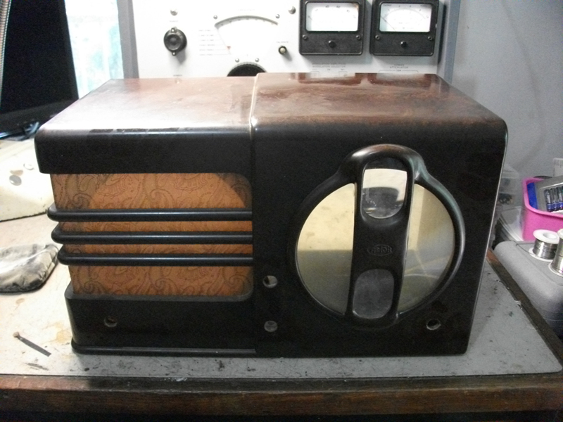 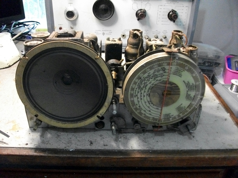 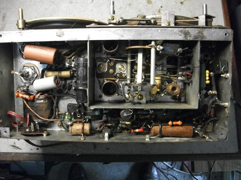  |
|
|
Return to top of page · Post #: 2 · Written at 2:41:50 PM on 18 March 2016.
|
|

|
Location: Sydney, NSW
Member since 28 January 2011 Member #: 823 Postcount: 6949 |
|
A few sets of the late 1930s had that or similar lineups. The 2 x 6B7 seems unusual -- maybe Astor or Monarch. |
|
|
Return to top of page · Post #: 3 · Written at 5:16:10 PM on 18 March 2016.
|
|

|
Location: Wangaratta, VIC
Member since 21 February 2009 Member #: 438 Postcount: 5715 |
|
More likely 6D6 as a first IF is more believable and that is not pin compatible with 6B7. |
|
|
Return to top of page · Post #: 4 · Written at 5:29:40 PM on 18 March 2016.
|
|
|
|
Location: Sydney, NSW
Member since 28 January 2011 Member #: 823 Postcount: 6949 |
|
Yes, plenty of candidates if it's meant to be a 6D6. Photo needed in that case. |
|
|
Return to top of page · Post #: 5 · Written at 10:51:52 PM on 18 March 2016.
|
|

|
Administrator
Location: Naremburn, NSW
Member since 15 November 2005 Member #: 1 Postcount: 7624 |
|
Astor Aladdin. Not sure of the model number. ‾‾‾‾‾‾‾‾‾‾‾‾‾‾‾‾‾‾‾‾‾‾‾‾‾‾‾‾‾‾‾‾‾‾‾‾‾‾‾‾‾‾‾‾‾‾‾‾‾‾‾‾‾‾‾‾‾‾‾‾‾‾‾‾‾‾‾‾ A valve a day keeps the transistor away... |
|
|
Return to top of page · Post #: 6 · Written at 11:03:35 PM on 18 March 2016.
|
|
|
|
Location: Sydney, NSW
Member since 28 January 2011 Member #: 823 Postcount: 6949 |
|
Okay, as it's an Astor mantel, the valve line-up as given appears to be correct for either a model GA (1937) or a model CF (1938), with one of those valves being a 6B7S. |
|
|
Return to top of page · Post #: 7 · Written at 11:49:07 PM on 18 March 2016.
|
|

|
Location: Hill Top, NSW
Member since 18 September 2015 Member #: 1801 Postcount: 2253 |
|
That should come up nicely once the chassis etc is cleaned, and those old caps replaced. |
|
|
Return to top of page · Post #: 8 · Written at 7:16:59 PM on 19 March 2016.
|
|

|
Location: Latham, ACT
Member since 21 February 2015 Member #: 1705 Postcount: 2228 |
|
Found this one on ebay:- |
|
|
Return to top of page · Post #: 9 · Written at 9:37:53 PM on 19 March 2016.
|
|
|
|
Location: Wangaratta, VIC
Member since 21 February 2009 Member #: 438 Postcount: 5715 |
|
That set has been worked on before, one of those wets looks like it is insulated from the chassis. That indicates back bias (which it has) & that needs to be checked to see that it is wired as it should be. |
|
|
Return to top of page · Post #: 10 · Written at 11:04:01 AM on 20 March 2016.
|
|
|
|
Location: Tynong North, VIC
Member since 9 April 2009 Member #: 464 Postcount: 37 |
|
Thanks for your replies , and thanks GTC for the circuit diagram ,the set is a little different to most with three IF transformers, |
|
|
Return to top of page · Post #: 11 · Written at 12:51:57 PM on 20 March 2016.
|
|
|
|
Location: Sydney, NSW
Member since 28 January 2011 Member #: 823 Postcount: 6949 |
|
Always happy to help where I can. |
|
|
« Back ·
1 ·
Next »
|
|
|
You need to be a member to post comments on this forum.
|
|
Sign In
Vintage Radio and Television is proudly brought to you by an era where things were built with pride and made to last.
DISCLAIMER: Valve radios and televisions contain voltages that can deliver lethal shocks. You should not attempt to work on a valve radio or other electrical appliances unless you know exactly what you are doing and have gained some experience with electronics and working around high voltages. The owner, administrators and staff of Vintage Radio & Television will accept no liability for any damage, injury or loss of life that comes as a result of your use or mis-use of information on this website. Please read our Safety Warning before using this website.
WARNING: Under no circumstances should you ever apply power to a vintage radio, television or other electrical appliance you have acquired without first having it checked and serviced by an experienced person. Also, at no time should any appliance be connected to an electricity supply if the power cord is damaged. If in doubt, do not apply power.
Shintara - Keepin' It Real · VileSilencer - Maintain The Rage