|
Kriesler 11 20 some questions please
|
|
« Back ·
1 ·
Next »
|
|
|

|
Location: Central Coast, NSW
Member since 18 April 2014
Member #: 1554
Postcount: 215
|
Hi All
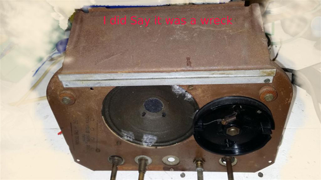
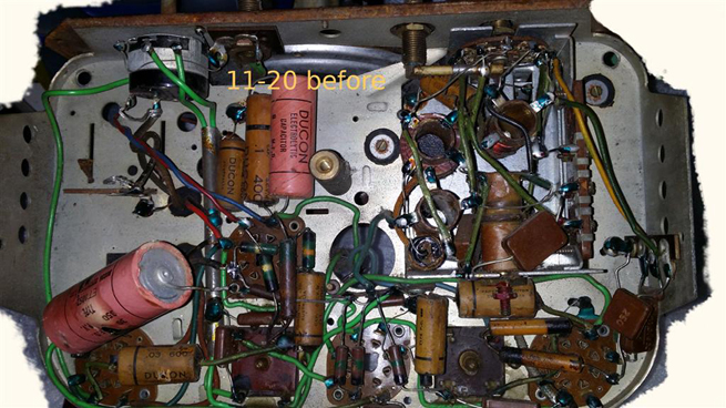
Well I got an 1120 chassis which is kinda in a poor state but seems it might be restorable and would serve as a bit of a test bench if I can get it going
So at this point I want to practice on it first before I do more work on the Bee (actually bee's)
sadly the Valves, well only one of the 2 maybe original to the set, the Audio valve.....so some questions if I may please
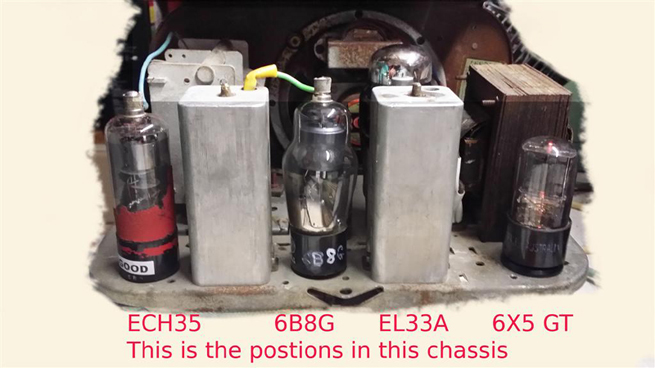
On the chassis the line up is stamped ECH35 (6G8G or 6B8G) EL33A & 6X5
I did grab the 1120 doc off Kevinchants website but there seemed to be no mention of changes to support either 6G8G or 6B8G, unless I missed something
Question 1
IF either a "6G8G or 6B8G" can be used, is there any rewiring or modification component wise that needs to be done to use each type ?
PDF;'s I found seem to support at lest partly this idea of interchangeability BUT
D1 & 2 seem to be transposed on each one for pins 4 & 5
6G8G
http://frank.pocnet.net/sheets/084/6/6G8G.pdf.
6B8G
http://frank.pocnet.net/sheets/127/6/6B7.pdf.
so is each diodes position critical for circuit operation?
not to mention what possible electrical differences may exist ?
Question 2
I want to retrofit a 6V6 Valve rather then the EL33A
So I just what to clarify what changes need to be made to support this
Seems this radio model wise was later fitted with the 6V6 Audio Valve and since these are a lot more easily obtainable and cheaper then an EL33A I want to retro fit a 6V6.... plus the 6V6 isnt as current hungry heater wise ...so saving a bit of juice from the transformer
I think what I need to know is in the Doc for this but its a bit all over the place read wise....
Bit of background on the set
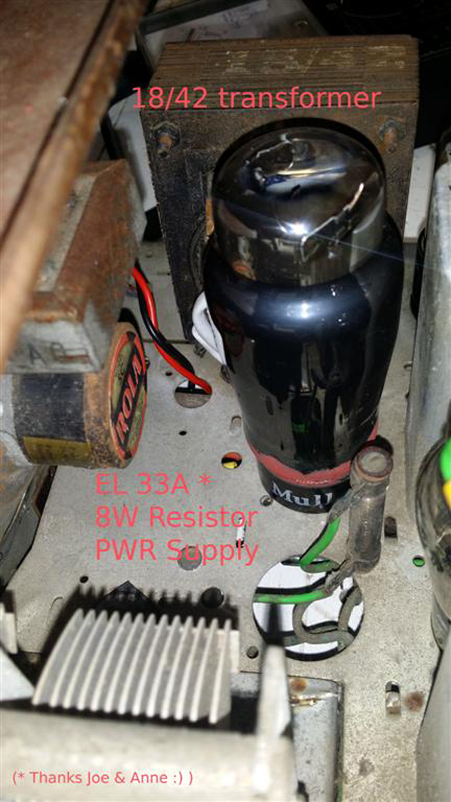
The Set uses an 18/42 power transformer which I believe is 250 AC HT each side (and the 6v3 heater winding)
I am pretty sure its a perm mag speaker and from what I understand the output transformer, thought probably not a perfect match will work for either tube.?
The power supply is using a 1500 Ohm 8W resistor (not the 6H choke) wried from 6X5 pin 8 (along with 30uf) other side goes to pin 4 of Audio tube socket, along with an 8μF Electro to GND and to somewhere else (haven't fully chased it to the schematic)
The output transformer is wired to pin 4 and pin 3 of the Audio Valve socket
The other Valve it come with was I "suspect" a 6A8G, (no markings) whether this was a retro fit, no Idea but its defiantly not an ECH35 as specified
The circuit looks original thought
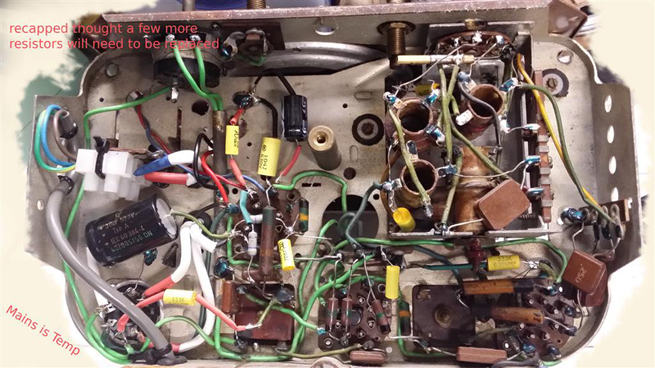
I have tested the power Transformer insulation wise and it seems OK...does need the usaul cap and out of Tolerance resistor work done on it
This one's really a bit of practical practice for me, but I am hopeful I can get this going with a little bit of help
Thank you for any help and advice you may have to give 
Cheers all
|
|
|
|
|

|
Location: Melbourne, VIC
Member since 20 September 2011
Member #: 1009
Postcount: 1263
|
Using a 6V6GT instead of a EL33 is possible, but will require some circuit modifications as there is a vast difference with the grid bias voltages. The original version of the 11-20 used the 6V6GT.
6B8G & 6G8G are similar in some aspects and either will probably work. ECH35's are more related to 6J8G's than 6A8G's.
Krieslers of that era were all over the place and had many changes and modifications over the life of production. There are exactly 27 versions of the 11-20. Do you know which one of the 27 is yours?
I will send out some additional service sheets for the 11-20, which includes a circuit diagram for the 6V6GT version.
|
|
|
|
|

|
Location: Wangaratta, VIC
Member since 21 February 2009
Member #: 438
Postcount: 5715
|
Some of the Krieslers built around WWII had a myriad of changes (one over 26). If you van get a copy of the circuits you will see the changes. I may have as I can remember doing a few ...? I have seen 3 on a bench & all were different.
As said 6V6 and EL3N (EL33) are not the same & 6V6 needs around double the grid bias.
6B8 & 6G8 are indeed similar. 6A8 has no triode and the other two are similar, but all three will work in the same hole with varying results in an Astor JJ .. J8 will compress the band. 6J8 is the SW tube.
Marc
|
|
|
|
|
|
|
Location: Central Coast, NSW
Member since 18 April 2014
Member #: 1554
Postcount: 215
|
Hi Monochrome625 And Marcc
Thanks so much for the feedback
Yes I am aware these things were all like a mixed bag of lollies and many changes, I surmise depending on what they could get their hands on at the time for the right price
The only info I have is the Kevin Chant Doc, this lists the output as a EL33A..its "issue 2" doc and starts circuit mods at model 11 20 G
I need to really put up an unhidden email on here I'll do that shortly*
*DONE this is an external email, so please use for general contact
Sadly I have no idea which version it is and can only guess at that once I chase through the doc looking at whats original in the Circuit and comparison to the notes...its a wreck really but looks mostly intact to originality
I had read I think it was at the Antique radio forum that the bias would need to be changed
to support 6V6 (if in fact it was using a EL33A in the first place) cant remember now which way but double/half yes ...think it was mention in that post for whatever it was 6V for one 12V (negative) for the other in that case
Edit just notice the Doc says -6V5 for the EL33A
So I take it no worries with either a 6"B"8G or 6"G"8G in the 2nd position IF/detec
either will work without circuit mods?
The 6V6 I do defiantly need to find the right circuit changes for
My guess is this involves R177 and possibly R153?...C26B position might be a clue here to track the model so I'll check exactly what the Values are of those resistors and how that caps hooked up
please excuse my complete noobness with this but I guess we all got to start somewhere and learn
Thanks again for the help
Cheers all
|
|
|
|
|
|
|
Location: Wangaratta, VIC
Member since 21 February 2009
Member #: 438
Postcount: 5715
|
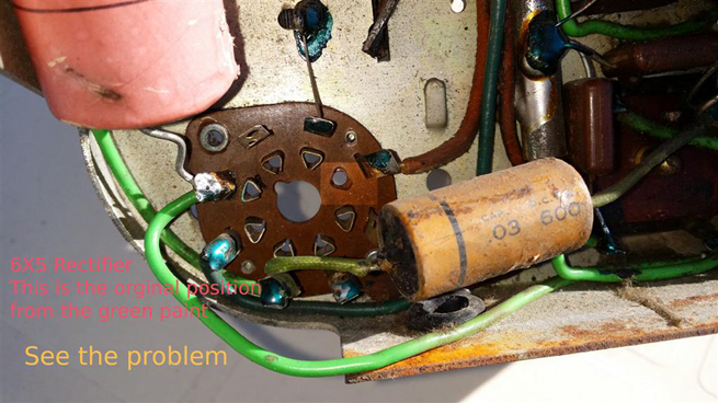
Kriesler often had green paint on factory connections. I am about to look for circuit but I am thinking AORSM may be the only one I have.
Beware of assumptions: They started these in 1948 & chopped & changed even adding minatures like 6AN7 & 6M5.
It would be best to list what is actually in it, make sure the circuit matches & then compare it to one with a 6V6. The sets are "back biased" so there will be no cathode resistor on the OP valve as it is set by the back bias and that bias development is dependent on circuit load (the current passing through it)
Marc
|
|
|
|
|
|
|
Location: Central Coast, NSW
Member since 18 April 2014
Member #: 1554
Postcount: 215
|
Thanks Marc
Yes as you say it is "back bias" like the Bee's setup and thats adding a little to my confusion for that very reason, it being current dependant for the voltage drops...anyway that aside (thought as you say, very critical I think to the aim of the exercise with the Audio Valve)
Yes the green paint helps a lot in IDing whats been touched lol...so I am kinda grateful for that
Seems only the 30μF (C110) was touched...and I think this is cactus from what I was told, not that Id use it anyway
I did find another schematic on the net which does list both "6V6 or EL33A" as the Audio Valve
but not what changes would be needed (yet to properly compare the schematics but they look pretty much the same and also component listing)
There is in the model changes notes in the kevinchants doc for model 11 20 O, same as 11 20 M and then it list the changes
first, is 6M5 replaced by 6V6
0.3 Meg grid leak to a 0.5 meg
50,000 Ohm blocking resistor deleted
Thought they dont reference the component ID's
they also do say to delete the 150 Ohm and replace with a 350 Ohm in the Bias
but yet another curve ball is they also say it has an "18/44 power transformer" with no details on what voltage HT it is...so humm...I could hope its a typo as they do list another power transformer 18-7 with 275 Volts either side of Centre Tap (18/42 is 250V per side)
Also a comment Errata, with ref to issue 1
"Typical Voltage Analysis"
6V6 GT :-
Cathode..=16 Volts DC. Should be "Grid Bias" = --16 Volts DC (neg)*
For the EL33A its states -- 6V5 (neg) Bias, in issue 2
(* its a little more then double but given the tolerances of the day I guess not so out of place)
Anyway your right!.... its best now to fully document what components are used and compare to the schematic & parts lists to see what changes there are actually in this chassis
I also have to power up the transformer to confirm its operating properly, thought it looks good on that front at this point ... Then replace the 6X5 socket as this was physically damaged when I got it, sadly
I've got some valves coming, if this ones a dud, well... they'll still be useful at some point anyway
Thank again Marc
Cheers all
|
|
|
|
|
|
|
Location: Wangaratta, VIC
Member since 21 February 2009
Member #: 438
Postcount: 5715
|
The back bias resistor change higher would be to get a bigger voltage for the 6V6 grid.
6V6 normally has a 50K grid stopper & a 500K grid leak & audio is fed into the middle of them. They are normally stuffed & need replacing and the plate resistors on 6B8 also have an attrition rate.
Some of the transformers are 220 - 0 - 220 and others 250 - 0 - 250ACV That may relate to to OP tube, it having a choke or the OP transformer, or compensation for the back bias change?
With the hot tubes OP & Rectifier I tend to replace sockets with Ceramic, if they have failed: They handle heat better.
Being a typical Australian circuit voltage info is scant. The European (Germanic) normally have valve element voltages & often current in tubes & rails: That was probably too useful for us.
Marc
|
|
|
|
|
|
|
Location: Melbourne, VIC
Member since 20 September 2011
Member #: 1009
Postcount: 1263
|
Between what I've just sent and Kevin Chant's we should now have most if not all of the documentation for the 11-20. AORSM Volumes 7 through to 10 also covers a fair bit of the 11-20 and the changes.
Kriesler 11-20 Service Manual
Update. Amendments for 11-20P to 11-20AA are here on this thread:
http://vintage-radio.com.au/default.asp?f=2&th=467.
Further update: The 18-44 power transformer HT winding taps are 250-CT-250.
|
|
|
|
|
|
|
Location: Central Coast, NSW
Member since 18 April 2014
Member #: 1554
Postcount: 215
|
|
|
|
|
|
|
|
Location: Wangaratta, VIC
Member since 21 February 2009
Member #: 438
Postcount: 5715
|
If the first cap is lowered on the choke input filter that lowers the voltage on B+ & the stress on the 6X5. Those had a bad reputation as some designs of them has a notorious habit of shorting internally.
From memory some of those Kriesler's had a double filter cap and some times three.
With simple "back bias" all of the current of all of the cathodes passes through it and that is what develops the volts across it. So you end up with the CT being the most negative point and the chassis positive relative to the CT.
If you happen to know the sum total of all of the plates & screen current, or the current draw you can predict what the voltage should be. The other thing is that if the grid leak of the OP tube goes to the CT then you know what current the set draws to get the correct grid bias voltage for the OP tube at the particular B+
There is actually logic in all of this apparent mess.
Marc
I did forget 6B8 & 6G8: Those tubes should be pin interchangeable, hence no comment & they appear listed as the do.
|
|
|
|
|
|
|
Location: Central Coast, NSW
Member since 18 April 2014
Member #: 1554
Postcount: 215
|
Hi Marc, All
Yes well aware of the 6X5 History, they seem quite a popular rectifier in Oz radios thought.
I got a few X plate GE (short bottles) that I hope aren't in the category of the shorting variety
(Be nice to know exactly which design in the GT series apart from the original "6X5 over under" one that are more prone to failure)
They test Well thought so they will be what I use
I read that the X plate are probably a safer bet, still there are quite a few versions of design that brought there own possible faults to the table .....and even the X style has a couple (that I know) different designs...there's a thread or 3 over at the Antique forums on them...worth a read for anyone interested in the details..
Thanks for the tips on how that back bias works too marc, I am getting the idea its just little harder to follow with radio circuits as it seems you really need to follow the "leg bone connected to the hip bone" with them..its not a case of just hanging between a +V Gnd and -V like you often see with semiconductor circuits
Even a guitar valve amp is liable to have purpose build negative supply, a lot of the time a negative voltage doubler, So I am guessing for costs its was rather clever how it was done with those old radios
Yes the power supply does vary a bit and the original version it seems does have 3 caps...with the tapped resistor
BTW yes defiantly, the 6X5 was in the outer position by the transformer from day one , the green paint supports this...this maybe a trap for the unwary....Not sure whats going to happen if you plug an Audio tube in there but I guess it cant be good!
Thanks again for that with the 6G8G...and 6B8G
Oddly I just check the other non working Bee I got and it had a 6"B"8G in that position...judging by the amount of work I had to do to remove it its been in there along time but this set had had work done on it so its not conclusive of being an original tube...sadly no model stamp so anybodies guess at model version.. must be later thought as its using wafer sockets...and an ECH35 converter
From what I understand the Wafer socket come later in manufacture of these things ? but open to correction on that
Anyway you both given me enough to work with so I'll post back in this thread when I got something useful to say about it
Thank again, Cheers
|
|
|
|
|
|
|
Location: Central Coast, NSW
Member since 18 April 2014
Member #: 1554
Postcount: 215
|
|
|
|
|
|
|
|
Location: Central Coast, NSW
Member since 18 April 2014
Member #: 1554
Postcount: 215
|
Just an Update
I did actually find a case... not perfect but good enough
just waiting on a bit of cloth from Steve to redo the top vent ...the speaker grill cloth is original and survived the wash so think I'll leave it even if it isnt so pretty...of two minds on that thought
Sadly the chassis had been well pillaged but I may have got a spare power transformer out of it
when done I'll get a photo posted up
|
|
|
|
« Back ·
1 ·
Next »
|
|
You need to be a member to post comments on this forum.
|