Welcome to Australia's only Vintage Radio and Television discussion forums. You are not logged in. Please log in below, apply for an account or retrieve your password.
Australian Vintage Radio Forums
  Home  ·  About Us  ·  Discussion Forums  ·  Glossary  ·  Outside Links  ·  Policies  ·  Services Directory  ·  Safety Warnings  ·  Tutorials

Tech Talk

Forum home - Go back to Tech talk

 Loop antenna and alignment
« Back · 1 · 2 · Next »
 Return to top of page · Post #: 1 · Written at 6:31:25 PM on 8 December 2013.
Maven's Gravatar
 Location: Canberra, ACT
 Member since 23 August 2012
 Member #: 1208
 Postcount: 584

Before I finish aligning my Philips 179, I'm testing loop antennae. The reason is that I have found loops give much better suppression of electronic hash. I have neighbours on three sides with large solar arrays on their roofs. The DC-AC inverters seem to create a lot of background hash, not to mention my own household noise.

I"ve tested a flat loop as built in to a 1956 portable, a ferrite-core loop from a modern portable, and a 25cm diameter 24-loop circular antenna made from DIY instructions found online. They all work better than long-wire.

The DIY loop gives best hash suppression BUT it biases sensitivity of the 179 quite strongly toward the centre of the MW band, so that signals at either end are noticeably weaker.

I have adjusted the MW oscillator trimmer so that tuning is correctly spaced across the dial. The antenna trimmer seems to make little difference. I haven't touched IFT trimmers yet (they are heavily waxed). The antenna and oscillator coil slugs can be accessed from above the chassis, but are also waxed so I am cautious about attacking them.

Which of the alignment parameters is most likely to be the cause of biased sensitivity? Is it safe to poke around the antenna and oscillator coils (I have non-conductive alignment tools)?

Maven


 Return to top of page · Post #: 2 · Written at 7:17:44 PM on 8 December 2013.
Brad's avatar
 Administrator
 Location: Naremburn, NSW
 Member since 15 November 2005
 Member #: 1
 Postcount: 7301

If the tools have hard plastic tips or metal tips that are only exposed a millimetre or so then you should be right. Television alignment tool kits are made this way.

If standard screwdrivers are used then there will be a couple of issues - the alignment may not be accurate and the blade could short onto the metal can and in some cases this could cook the coil and you won't enjoy the rewind job that follows.


‾‾‾‾‾‾‾‾‾‾‾‾‾‾‾‾‾‾‾‾‾‾‾‾‾‾‾‾‾‾‾‾‾‾‾‾‾‾‾‾‾‾‾‾‾‾‾‾‾‾‾‾‾‾‾‾‾‾‾‾‾‾‾‾‾‾‾‾
A valve a day keeps the transistor away...

 
 Return to top of page · Post #: 3 · Written at 9:44:49 AM on 9 December 2013.
Art's Gravatar
 Art
 Location: Somewhere, USA
 Member since 22 October 2013
 Member #: 1437
 Postcount: 896

Is it an outdoor antenna, built into the radio, or indoors, but outside the radio?
I've wondered if the direction of the noise source could be blocked
with a partial Faraday cage... basically whether or not a Faraday "Fence" would work,
so long as the signal you want isn't coming in from the same direction.

400 Meter or so wave, it would take a fairly minimal complete cage to block the lot.


 Return to top of page · Post #: 4 · Written at 3:00:24 PM on 9 December 2013.
Maven's Gravatar
 Location: Canberra, ACT
 Member since 23 August 2012
 Member #: 1208
 Postcount: 584

As to Faraday cages - if I was doing radio astronomy or something like that I would look for that level of protection, but it might be cheaper to move house.

I've made progress with alignment.

Removing wax took about an hour. I started with dentists picks. I keep a cheap set bought online for all kinds of fine tool work. I had to excavate about 1cm plug of wax out of a 4mm hole to access the MW oscillator lug. After all the digging, cleaned up where possible with soldering iron and paper towel. Place a bit of towel on the wax and dab with the iron - the towel absorbs it like solder wick and nobody gets hurt. Kept hot iron away from plastic threaded items.

Trying to "peak" IFT2 as instructed, I couldn't see any sign of change in signal with the prescribed 100pf bypass to ground.

Adjusting IFT1 and MW osc slug, trimmer, and antenna trimmer, eventually got acceptable reception with stations properly spaced across the dial, and then went back to IFT2 and adjusted for strongest audio signal. Strong stations now give very clear signal, with minimal hash background. Using my DIY loop made from 4 circuits of 6-way flat telephone cable, two ends of each wire in the cable joined, offset to create a single 24-loop circuit.

Thus:

a =pos lead
b=a
c=b
d=c
e=d
f=e
neg lead = f


I found it worked better for the low end of the band when I put 100pf capacitor across the ends of the loop. The cable is not mounted on a frame, but held togther and in a reasonably circular loop by being wrapped in a plastic flexible spiral cable tidy that I had lying around. At the moment it just hands on a hook above the chassis - in due course it will be inside a cabinet.

Higher frequency stations are received more weakly, but they also transmit on lower wattage than the lower end of the band.

I also doubt that AGC is functioning properly, but can't see why, now that alignment seems pretty good.

More study to do on that - tips anyone?


 Return to top of page · Post #: 5 · Written at 5:49:18 PM on 9 December 2013.
Tinkera123's Gravatar
 Location: Melbourne, VIC
 Member since 5 October 2009
 Member #: 555
 Postcount: 465

Hi Maven,

Are you using Signal generator, scope, multimeter, or aligning by ear??
Are you following a Manufacturers instructions or using basic principles??
The critical issue is to follow the logical process. I can dig out a couple of 'aligning' articles if you need them.

Re AGC - trace the circuit, check component values, disconnect it and tune to a strong station, reconnect, you should hear a drop in volume. Or try tuning across a strong station while monitoring AGC voltage. Should be only a couple of volts, negative. I sometimes disconnect AGC to 'align' so as to avoid feedback into the earlier stage(s), or sometimes monitor the AGC for strongest signal (provided the AGC circuit is not loaded too much).

My apologies if you already know this stuff ....

Cheers,
Ian


‾‾‾‾‾‾‾‾‾‾‾‾‾‾‾‾‾‾‾‾‾‾‾‾‾‾‾‾‾‾‾‾‾‾‾‾‾‾‾‾‾‾‾‾‾‾‾‾‾‾‾‾‾‾‾‾‾‾‾‾‾‾‾‾‾‾‾‾
Cheers, Ian

 
 Return to top of page · Post #: 6 · Written at 8:36:53 PM on 9 December 2013.
Maven's Gravatar
 Location: Canberra, ACT
 Member since 23 August 2012
 Member #: 1208
 Postcount: 584

No sig generator.

Tried scope across IFT outputs but it seemed to introduce its own impedance issues and didn't show anything I couldn't hear.

Following instructions in Philips' service docs, but they assume one is a qualified serviceman and don't explain concepts such as "peak secondary on IFT2" - I guess it means detect maximum signal.

Any links to useful online articles would be appreciated.

Thanks for the suggestions about AGC checking - I'll follow those up. AGC on the 179 seems quite different to AGC on my other Philips 123.

Maven


 Return to top of page · Post #: 7 · Written at 7:45:23 AM on 10 December 2013.
Wa2ise's avatar
 Location: Oradell, US
 Member since 2 April 2010
 Member #: 643
 Postcount: 830

You may need to adjust the inductance of the antenna. With a loop that means adding or removing a turn or a fraction of a turn. With a ferrite rod you can slide the coil along the rod. Do this on a station near the bottom of the AM band, around say 558. After that, tune in a station near the top of the AM band and tweak the antenna trimmer. You may need to repeat. This should get tracking across the band, without touching the IF.


 Return to top of page · Post #: 8 · Written at 9:26:01 AM on 10 December 2013.
Marcc's avatar
 Location: Wangaratta, VIC
 Member since 21 February 2009
 Member #: 438
 Postcount: 5254

One does not put the CRO on the IFT: One puts it on the input to the volume, or OP tube.

Big mistake is to stuff too much signal in. According to Markus & Levy about 12mV PP at the antenna. That can be measured with the CRO but the point is, that you need an attenuator as the sig gens put out (in many cases) 10V +/_, a lot output via a cathode follower so DC isolation is desirable.

If you put too much signal in and swamp it, the AGC will cut in and you will never get the IFT trimmed. Some actually measure the AGC volts (high impedance meter) which will rise to its maximum at resonance.

Astors had a terminal on the plate of the OP valve to measure the voltage on the plate (see their alignment data)

Calibrating with a frequency counter can go awry if you feed it with modulated signal.

Methodology & the accuracy of the equipment are crucial factors

Marc


 Return to top of page · Post #: 9 · Written at 10:25:08 AM on 10 December 2013.
Tinkera123's Gravatar
 Location: Melbourne, VIC
 Member since 5 October 2009
 Member #: 555
 Postcount: 465

Hi Maven,

Two articles sent ..... pdf and Word documents ... one of which was provided to me by a member of this Forum.

... "and don't explain concepts such as "peak secondary on IFT2" - I guess it means detect maximum signal."

Correct. Alignment is achieved by maximising the signal in several LC resonant circuits ..... the secondary of IFT2 is such an LC resonant circuit, tuned via either a variable C or variable L, to the IF frequency.
The Primary of IFT2 is usually an LC resonant circuit also, inductively coupled to the Secondary, like a transformer.

Our old radios are full of resonant circuits ....

Cheers,
Ian


‾‾‾‾‾‾‾‾‾‾‾‾‾‾‾‾‾‾‾‾‾‾‾‾‾‾‾‾‾‾‾‾‾‾‾‾‾‾‾‾‾‾‾‾‾‾‾‾‾‾‾‾‾‾‾‾‾‾‾‾‾‾‾‾‾‾‾‾
Cheers, Ian

 
 Return to top of page · Post #: 10 · Written at 9:36:14 PM on 17 December 2013.
Maven's Gravatar
 Location: Canberra, ACT
 Member since 23 August 2012
 Member #: 1208
 Postcount: 584

I believe I have correct alignment now - all stations tuning at correct position on the dial.

I also have a loop antenna Mk II, 3 metres of 8-core flat phone cable wired to make a single 8-turn loop, tuned with a standard Jaycar 60-160pf tuning capacitor.

The loop is providing good noise suppression and good gain. Gain is greatly increased by also attaching a random wire antenna, which does not seem to introduce any more hash.

I still don't think AGC is working correctly, if at all. I've checked and replaced resistors and both B+ and bias voltage rails are correct.

AGC is supposed to be supplied from V3 (6BD7), but I can't work out how V3 is feeding AGC signal back to the grid of V2. Does it pull down the bias on secondary grids of both V1 and V2? If so, which resistors are most critical?

The relevant part of the schematic is here:

http://thwaites.homemail.com.au/audio/179%20partial%20schematic.jpg.

Maven


 Return to top of page · Post #: 11 · Written at 11:11:15 AM on 18 December 2013.
Marcc's avatar
 Location: Wangaratta, VIC
 Member since 21 February 2009
 Member #: 438
 Postcount: 5254

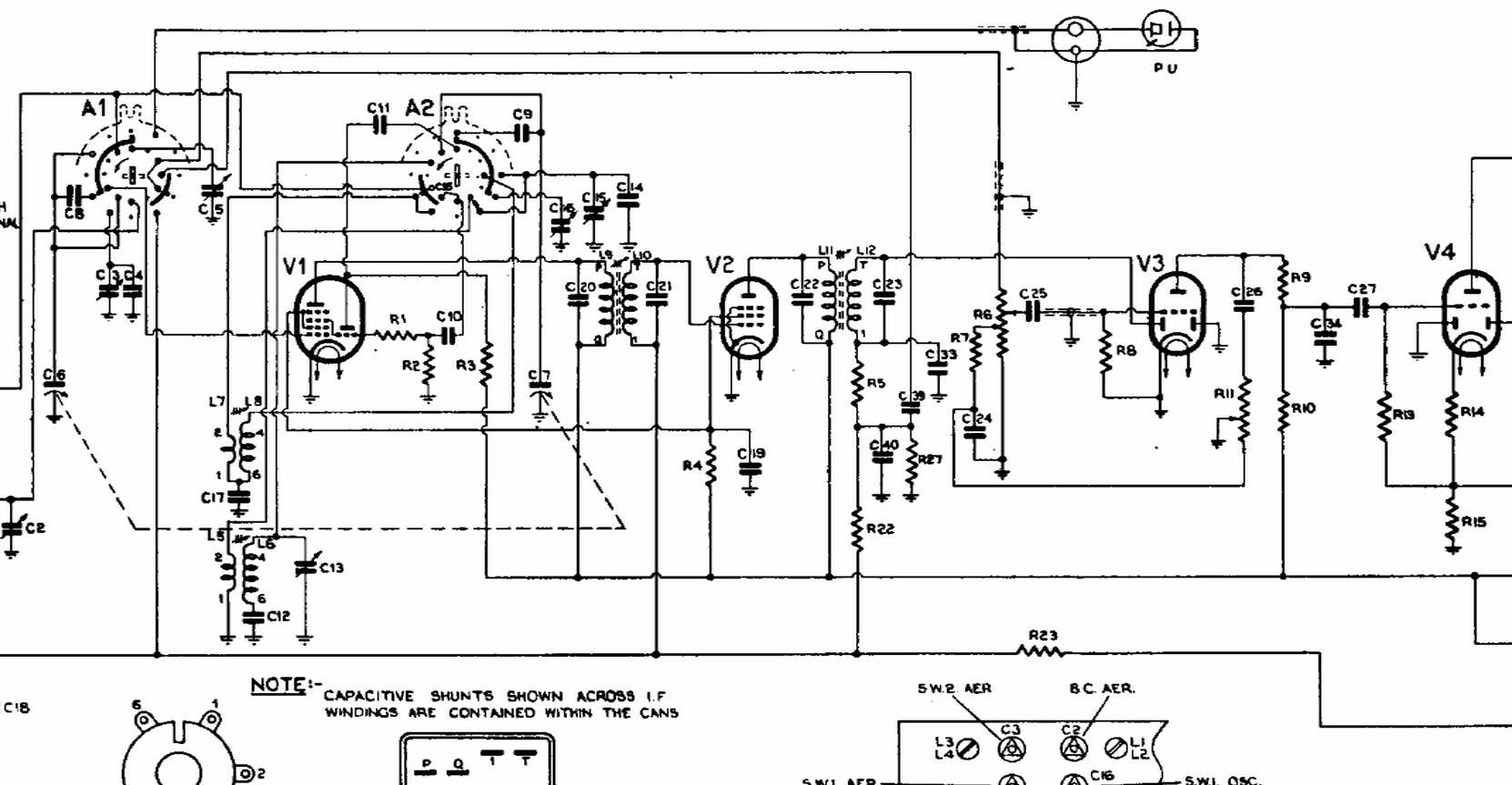
AGC / AVC does not pull down? I cannot see all of the AGC circuit?

AVC develops a negative DC voltage The DC path is via the IFT coil. AGC is applied to more than one valve

R27 & R5 are a voltage divider; R22 & 23 are also on the rail which is incomplete after R23?

The increasing negative voltage produced by the diode plates is applied to the control grids. As the voltage increases it biases off the valves, desensitising them. This is why you cannot adjust the IFT properly with the AGC "cut in"; It will keep adjusting the signal strength, which is what it is supposed to do.

Getting an accurate AGC voltage is difficult Grids do not draw current and AGC is a high impedance circuit which can be loaded to meaningless by the loading effect of a voltmeter, that includes digital

Marc


 Return to top of page · Post #: 12 · Written at 11:56:28 AM on 18 December 2013.
Maven's Gravatar
 Location: Canberra, ACT
 Member since 23 August 2012
 Member #: 1208
 Postcount: 584

Sorry I put up only partial schematic - misguided attempt to narrow the problem.

It's informative that the path is via the IFT - I didn't see how that could work, since it looks like it goes to the secondary.

For reference, I've now put up the whole of the 179 service docs:

RadioPlayer179


 Return to top of page · Post #: 13 · Written at 5:49:50 PM on 18 December 2013.
Gandhn's Gravatar
 Location: Cameron Park, NSW
 Member since 5 November 2010
 Member #: 770
 Postcount: 388

The valves that have AGC (or AVC in older terminology) applied get their standing negative bias from the voltage drop across R24 in your circuit.
On stronger signals, this is added to as described by Marcc, biasing them more to reduce their gain. As the grid does not draw any current, the grid is at a negative potential that is the sum of the back bias, (R24) and any AGC voltage. The IF transformer secondary is generally only a few ohms resistance, virtually nothing relative to the other resistors in the AGC circuit, so has no effect on the DC condition.
It is sometimes a difficult concept to understand, I hope this helps.
Harold


 Return to top of page · Post #: 14 · Written at 7:56:29 PM on 18 December 2013.
Marcc's avatar
 Location: Wangaratta, VIC
 Member since 21 February 2009
 Member #: 438
 Postcount: 5254

The point is that DC is not affected by the resonance of the coil as it has for the purpose of this exercise no frequency. It sees the coil, only as a small resistance.

It is not at all unusual (as happens in reflexed sets) to have RF, AF. (or both) and DC all present in one valve.Some valves can multi-skill 6BL8 is actually a frequency changer & it's found in a myriad of places, including audio.

What you are also looking at is a delayed AGC/AVC the diode plate on V3 is not principally detecting the audio, if we looked at V4 we will likely see that its diode plate is exclusively used for the audio detector.

Marc


 Return to top of page · Post #: 15 · Written at 9:29:53 PM on 18 December 2013.
Maven's Gravatar
 Location: Canberra, ACT
 Member since 23 August 2012
 Member #: 1208
 Postcount: 584

Thanks both - I think I now understand the theory of operation, and need to
1) disconnect the AGC voltage connection between V3 and the IFT.
2) put an oscilliscope on the V3 diode output and see that some DC voltage (negative?) is varying with tuning of stations of different known strengths. If not, maybe a faulty valve at V3?
3) observe whether variance in station output volumes is significantly different to when the AGC was connected.
4) go through the alignment procedure again, with AGC disconnected.
5) reconnect AGC and perhaps finesse padding and oscillator if needed.

Spousal obligations are steadily rising in pitch as seasonal deadlines loom, so workshop time may be more limited for a few days...

Maven


« Back · 1 · 2 · Next »
 You need to be a member to post comments on this forum.

Sign In

Username:
Password:
 Keep me logged in.
Do not tick box on a computer with public access.