
Tech Talk
Forum home - Go back to Tech talk
|
Loop antenna and alignment
|
|
|
Return to top of page · Post #: 16 · Written at 10:46:09 PM on 18 December 2013.
|
|

|
Location: Wangaratta, VIC
Member since 21 February 2009 Member #: 438 Postcount: 5557 |
|
There is no need to totally disconnect the AGC. That risks cutting off signal. Some actually use it to get the best signal strength & set that way. Astor sets (as before) often have a plug at the back to take a meter probe and multi-meters like Peak 200H have a blocking cap on a separate socket just for that method. |
|
|
Return to top of page · Post #: 17 · Written at 9:37:05 PM on 22 December 2013.
|
|
|
|
Location: Somewhere, USA
Member since 22 October 2013 Member #: 1437 Postcount: 896 |
|
What I meant initially was, a grounded shield partially covering the loop antenna in the direction you think the noise is coming from. Why is it more expensive to move house? |
|
|
Return to top of page · Post #: 18 · Written at 9:48:39 PM on 22 December 2013.
|
|
|
|
Location: Somewhere, USA
Member since 22 October 2013 Member #: 1437 Postcount: 896 |
|
If the radio doesn't have a ferrite loop antenna, and you have a spare one, |
|
|
Return to top of page · Post #: 19 · Written at 5:28:45 PM on 23 December 2013.
|
|
|
|
Location: NSW
Member since 10 June 2010 Member #: 681 Postcount: 1353 |
|
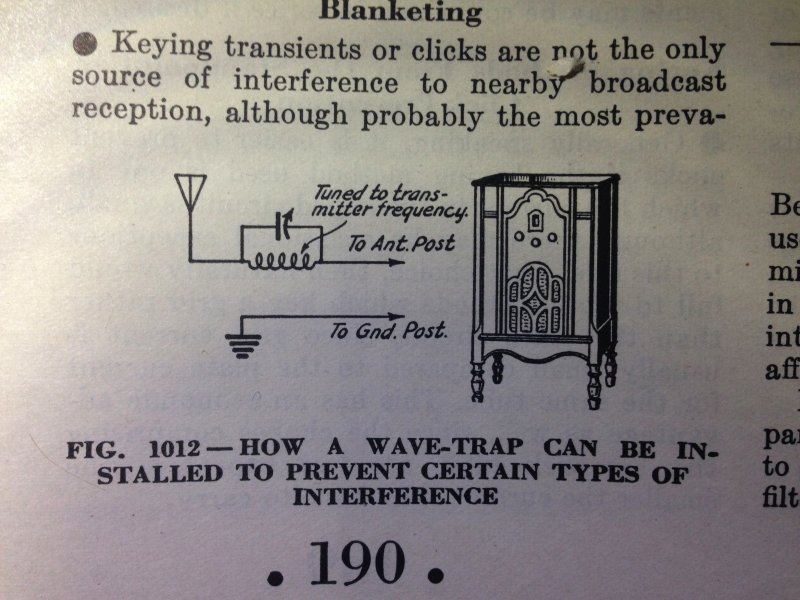
As loop antennas work by picking up the magnetic component of an electromagnetic wave, they can be shielded against electric field interference with a metal shield wrapped around the full circumference of the loop. A small gap is needed at some point in the diameter of the loop so that the shield doesn't make a shorted turn for the magnetic field part of the signal. |
|
|
Return to top of page · Post #: 20 · Written at 9:06:33 PM on 23 December 2013.
|
|
|
|
Location: Somewhere, USA
Member since 22 October 2013 Member #: 1437 Postcount: 896 |
|
I'm about to try pointing one at Amberley airbase near Ipswich (Qld). |
|
|
Return to top of page · Post #: 21 · Written at 9:54:33 PM on 23 December 2013.
|
|
|
|
Location: Wangaratta, VIC
Member since 21 February 2009 Member #: 438 Postcount: 5557 |
|
Maybe you are in the path of the ILS, or Radar. The latter would tend to be uneven in signal strength but regular in the variance of its rise & fall. That would be picked ap by the AGC voltage rising & falling like a grandfather clock ticking. |
|
|
Return to top of page · Post #: 22 · Written at 12:56:19 AM on 24 December 2013.
|
|
|
|
Location: Somewhere, USA
Member since 22 October 2013 Member #: 1437 Postcount: 896 |
|
Was that directed at me? I'm deliberately trying to receive it. |
|
|
Return to top of page · Post #: 23 · Written at 6:56:00 AM on 24 December 2013.
|
|
|
|
Location: Harston, VIC
Member since 28 February 2009 Member #: 442 Postcount: 145 |
|
Hi All, |
|
|
Return to top of page · Post #: 24 · Written at 12:13:06 PM on 11 March 2014.
|
|
|
|
Location: Somewhere, USA
Member since 22 October 2013 Member #: 1437 Postcount: 896 |
|
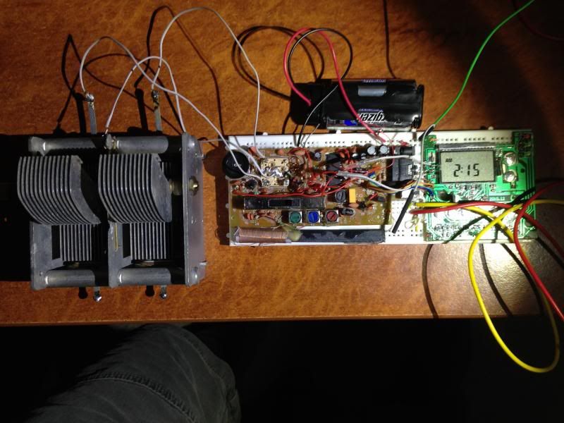
Since interference from switchmode solar gear was mentioned, |
|
|
Return to top of page · Post #: 25 · Written at 11:48:24 PM on 11 March 2014.
|
|
|
|
Location: Wangaratta, VIC
Member since 21 February 2009 Member #: 438 Postcount: 5557 |
|
Where you can get into strife is being too close to a major airfield. The TV can often tell you. |
|
|
You need to be a member to post comments on this forum.
|
|
Sign In
Vintage Radio and Television is proudly brought to you by an era where things were built with pride and made to last.
DISCLAIMER: Valve radios and televisions contain voltages that can deliver lethal shocks. You should not attempt to work on a valve radio or other electrical appliances unless you know exactly what you are doing and have gained some experience with electronics and working around high voltages. The owner, administrators and staff of Vintage Radio & Television will accept no liability for any damage, injury or loss of life that comes as a result of your use or mis-use of information on this website. Please read our Safety Warning before using this website.
WARNING: Under no circumstances should you ever apply power to a vintage radio, television or other electrical appliance you have acquired without first having it checked and serviced by an experienced person. Also, at no time should any appliance be connected to an electricity supply if the power cord is damaged. If in doubt, do not apply power.
Shintara - Keepin' It Real · VileSilencer - Maintain The Rage