
Tech Talk
Forum home - Go back to Tech talk
|
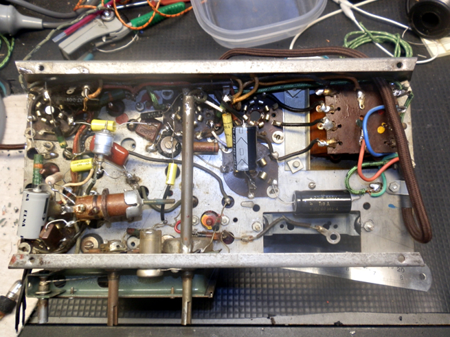
Tasma 1001 under chassis layout drawing
|
|
|
Return to top of page · Post #: 1 · Written at 10:39:35 AM on 4 November 2013.
|
|

|
Location: Perth, WA
Member since 19 November 2008 Member #: 381 Postcount: 240 |
|
Hi, |
|
|
Return to top of page · Post #: 2 · Written at 11:18:49 AM on 4 November 2013.
|
|

|
Location: Sydney, NSW
Member since 28 January 2011 Member #: 823 Postcount: 6946 |
|
I don't have a drawing, but I'd be taking lots of in-focus and well-lit photos, too. |
|
|
Return to top of page · Post #: 3 · Written at 1:30:14 PM on 4 November 2013.
|
|
|
|
Location: Somewhere, USA
Member since 22 October 2013 Member #: 1437 Postcount: 896 |
|
The drawing leaves potential for Human error, |
|
|
Return to top of page · Post #: 4 · Written at 2:45:40 PM on 4 November 2013.
|
|
|
|
Location: Perth, WA
Member since 19 November 2008 Member #: 381 Postcount: 240 |
 I'll do a drawing as well in the near future. I want to wire a new harness into the radio and lace it up like I used to do back in my PMG days in the 60's. |
|
|
Return to top of page · Post #: 5 · Written at 2:59:50 PM on 4 November 2013.
|
|
|
|
Location: Sydney, NSW
Member since 28 January 2011 Member #: 823 Postcount: 6946 |
|
lace it up like I used to do back in my PMG days in the 60's. |
|
|
Return to top of page · Post #: 6 · Written at 3:31:27 PM on 4 November 2013.
|
|
|
|
Location: Somewhere, USA
Member since 22 October 2013 Member #: 1437 Postcount: 896 |
|
If you are actually desoldering the entire chassis, |
|
|
Return to top of page · Post #: 7 · Written at 4:49:43 PM on 4 November 2013.
|
|
|
|
Location: Perth, WA
Member since 19 November 2008 Member #: 381 Postcount: 240 |
|
The chassis on this radio is not to bad. Its painted green and if I repainted it I will lose the transfers and detalis on the back so I think I'll just rewire it with the period type braided wire. I will post before and after photos to hopefully inspire others. |
|
|
Return to top of page · Post #: 8 · Written at 4:56:27 PM on 4 November 2013.
|
|
|
|
Location: Somewhere, USA
Member since 22 October 2013 Member #: 1437 Postcount: 896 |
|
Well I suppose I just incorrectly assumed it was in poor condition. |
|
|
Return to top of page · Post #: 9 · Written at 5:15:11 PM on 4 November 2013.
|
|
|
|
Location: NSW
Member since 10 June 2010 Member #: 681 Postcount: 1406 |
|
ARTS&P stickers are fragile in my experience and bits can fall of even with careful handling. So now spray them with a couple of mist coats of clear matte lacquer that my ladies use for craft work. Mask all around first. |
|
|
Return to top of page · Post #: 10 · Written at 6:04:32 PM on 4 November 2013.
|
|

|
Location: Tamworth, NSW
Member since 6 April 2012 Member #: 1126 Postcount: 472 |
|
PVA Wood glue is also good to preserve labels/stickers. |
|
|
Return to top of page · Post #: 11 · Written at 7:21:07 PM on 4 November 2013.
|
|
|
|
Location: Somewhere, USA
Member since 22 October 2013 Member #: 1437 Postcount: 896 |
|
Lol |
|
|
Return to top of page · Post #: 12 · Written at 9:30:58 PM on 4 November 2013.
|
|

|
Location: Wangaratta, VIC
Member since 21 February 2009 Member #: 438 Postcount: 5703 |
|
If the chassis is ferrous, you can always cut a fridge magnet to size and use that for a mask. |
|
|
Return to top of page · Post #: 13 · Written at 9:53:18 PM on 4 November 2013.
|
|
|
|
Location: Canberra, ACT
Member since 23 August 2012 Member #: 1208 Postcount: 587 |
|
When I did a job like this recently on a 3D ratsnest of a radio, I tried to colour-code the wiring as much as possible, visually distinguishing B+ from heater rail from audio etc. I fell in love with spaghetti tubing combined with solid copper wire that could hold a shape on an indirect route rather than just sagging across the shortest route from point to point. |
|
|
Return to top of page · Post #: 14 · Written at 11:09:06 AM on 5 November 2013.
|
|
|
|
Location: Wangaratta, VIC
Member since 21 February 2009 Member #: 438 Postcount: 5703 |
|
You can get cloth covered wire in solid core. Green is normally heaters. When not following an existing scheme. |
|
|
Return to top of page · Post #: 15 · Written at 6:20:08 PM on 5 November 2013.
|
|
|
|
Location: Perth, WA
Member since 19 November 2008 Member #: 381 Postcount: 240 |
|
Hi Maven, |
|
|
You need to be a member to post comments on this forum.
|
|

Sign In
Vintage Radio and Television is proudly brought to you by an era where things were built with pride and made to last.
DISCLAIMER: Valve radios and televisions contain voltages that can deliver lethal shocks. You should not attempt to work on a valve radio or other electrical appliances unless you know exactly what you are doing and have gained some experience with electronics and working around high voltages. The owner, administrators and staff of Vintage Radio & Television will accept no liability for any damage, injury or loss of life that comes as a result of your use or mis-use of information on this website. Please read our Safety Warning before using this website.
WARNING: Under no circumstances should you ever apply power to a vintage radio, television or other electrical appliance you have acquired without first having it checked and serviced by an experienced person. Also, at no time should any appliance be connected to an electricity supply if the power cord is damaged. If in doubt, do not apply power.
Shintara - Keepin' It Real · VileSilencer - Maintain The Rage