
Tech Talk
Forum home - Go back to Tech talk
|
Tasma 1001 under chassis layout drawing
|
|
|
Return to top of page · Post #: 16 · Written at 6:50:58 PM on 5 November 2013.
|
|
|
|
Location: Somewhere, USA
Member since 22 October 2013 Member #: 1437 Postcount: 896 |
|
Continuity tester is always good |
|
|
Return to top of page · Post #: 17 · Written at 8:23:35 PM on 5 November 2013.
|
|

|
Location: Sydney, NSW
Member since 28 January 2011 Member #: 823 Postcount: 6688 |
|
they use spare pins on the octal valve sockets as junction points |
|
|
Return to top of page · Post #: 18 · Written at 10:11:08 AM on 24 November 2013.
|
|

|
Location: Perth, WA
Member since 19 November 2008 Member #: 381 Postcount: 240 |
|
I have found that the local oscillator coil in my Tasma is not the original! Any ideas were I can get the correct one? |
|
|
Return to top of page · Post #: 19 · Written at 12:02:13 PM on 24 November 2013.
|
|
|
|
Location: Somewhere, USA
Member since 22 October 2013 Member #: 1437 Postcount: 896 |
|
But if you're not painting the chassis, can't you do the new wiring one by one? |
|
|
Return to top of page · Post #: 20 · Written at 1:06:08 PM on 24 November 2013.
|
|
|
|
Location: Canberra, ACT
Member since 23 August 2012 Member #: 1208 Postcount: 584 |
|
The Kicad open-source electronics CAD program has libraries of component images to represent analogue radio schematics, as well as for digitial circuit design. See this link for an Australian source: http://www.philipstorr.id.au/radio/eighteen/kicad.htm. |
|
|
Return to top of page · Post #: 21 · Written at 6:00:43 PM on 24 November 2013.
|
|
|
|
Location: Perth, WA
Member since 19 November 2008 Member #: 381 Postcount: 240 |
|
I use Visio do do the drawings. Here is the result so far: 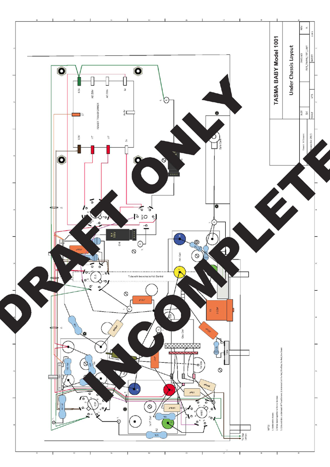 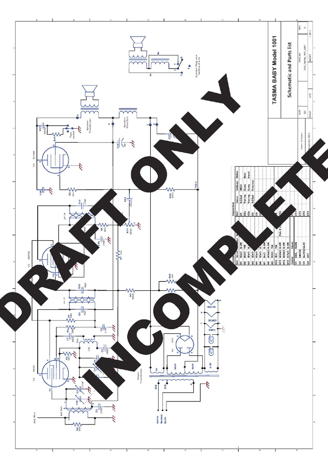 |
|
|
Return to top of page · Post #: 22 · Written at 6:24:03 PM on 24 November 2013.
|
|
|
|
Location: Somewhere, USA
Member since 22 October 2013 Member #: 1437 Postcount: 896 |
|
You need to Photobucket images, and then post the link here. |
|
|
Return to top of page · Post #: 23 · Written at 6:42:40 PM on 24 November 2013.
|
|

|
Administrator
Location: Naremburn, NSW
Member since 15 November 2005 Member #: 1 Postcount: 7307 |
|
He sent them to me. ‾‾‾‾‾‾‾‾‾‾‾‾‾‾‾‾‾‾‾‾‾‾‾‾‾‾‾‾‾‾‾‾‾‾‾‾‾‾‾‾‾‾‾‾‾‾‾‾‾‾‾‾‾‾‾‾‾‾‾‾‾‾‾‾‾‾‾‾ A valve a day keeps the transistor away... |
|
|
Return to top of page · Post #: 24 · Written at 6:52:54 PM on 24 November 2013.
|
|
|
|
Location: Canberra, ACT
Member since 23 August 2012 Member #: 1208 Postcount: 584 |
|
Those are certainly nice clear drawings - congratulations. I wouldn't suggest you start again in Kicad after all that good work. |
|
|
Return to top of page · Post #: 25 · Written at 8:04:08 PM on 24 November 2013.
|
|
|
|
Location: Sydney, NSW
Member since 28 January 2011 Member #: 823 Postcount: 6688 |
|
He sent them to me. |
|
|
Return to top of page · Post #: 26 · Written at 9:11:50 PM on 24 November 2013.
|
|
|
|
Administrator
Location: Naremburn, NSW
Member since 15 November 2005 Member #: 1 Postcount: 7307 |
|
(as long as Brad doesn't change them) ‾‾‾‾‾‾‾‾‾‾‾‾‾‾‾‾‾‾‾‾‾‾‾‾‾‾‾‾‾‾‾‾‾‾‾‾‾‾‾‾‾‾‾‾‾‾‾‾‾‾‾‾‾‾‾‾‾‾‾‾‾‾‾‾‾‾‾‾ A valve a day keeps the transistor away... |
|
|
Return to top of page · Post #: 27 · Written at 5:35:11 PM on 27 November 2013.
|
|
|
|
Location: Perth, WA
Member since 19 November 2008 Member #: 381 Postcount: 240 |
|
Progress. 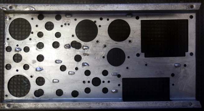 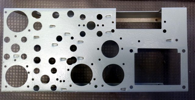 |
|
|
Return to top of page · Post #: 28 · Written at 6:02:08 PM on 27 November 2013.
|
|
|
|
Location: Sydney, NSW
Member since 28 January 2011 Member #: 823 Postcount: 6688 |
|
You've done a good job. It's not a task that I would ever consider doing. |
|
|
Return to top of page · Post #: 29 · Written at 12:18:15 AM on 28 November 2013.
|
|

|
Location: Wangaratta, VIC
Member since 21 February 2009 Member #: 438 Postcount: 5257 |
|
Fun job reverse engineering some of these. I am currently drawing the STC model 59 circuit now that I have it making radio noises. |
|
|
Return to top of page · Post #: 30 · Written at 10:12:41 AM on 28 November 2013.
|
|
|
|
Location: Perth, WA
Member since 19 November 2008 Member #: 381 Postcount: 240 |
|
Yes Marc, |
|
|
You need to be a member to post comments on this forum.
|
|


Sign In
Vintage Radio and Television is proudly brought to you by an era where things were built with pride and made to last.
DISCLAIMER: Valve radios and televisions contain voltages that can deliver lethal shocks. You should not attempt to work on a valve radio or other electrical appliances unless you know exactly what you are doing and have gained some experience with electronics and working around high voltages. The owner, administrators and staff of Vintage Radio & Television will accept no liability for any damage, injury or loss of life that comes as a result of your use or mis-use of information on this website. Please read our Safety Warning before using this website.
WARNING: Under no circumstances should you ever apply power to a vintage radio, television or other electrical appliance you have acquired without first having it checked and serviced by an experienced person. Also, at no time should any appliance be connected to an electricity supply if the power cord is damaged. If in doubt, do not apply power.
Shintara - Keepin' It Real · VileSilencer - Maintain The Rage