
Tech Talk
Forum home - Go back to Tech talk
|
PHILIPS MODEL 124 SCHEMATIC
|
|
|
Return to top of page · Post #: 16 · Written at 3:47:02 PM on 29 May 2023.
|
|

|
Location: Werribee South, VIC
Member since 30 September 2016 Member #: 1981 Postcount: 470 |
|
I don't think the volume pot would cause distortion. |
|
|
Return to top of page · Post #: 17 · Written at 7:53:24 PM on 29 May 2023.
|
|
|
|
Location: Belrose, NSW
Member since 31 December 2015 Member #: 1844 Postcount: 2375 |
|
What is the back bias voltage? |
|
|
Return to top of page · Post #: 18 · Written at 8:21:39 AM on 30 May 2023.
|
|

|
Location: Latham, ACT
Member since 21 February 2015 Member #: 1705 Postcount: 2158 |
|
Ian Robertson that I dont know but I have found two resistors ( 23ohm and 350 ohm ) on the same tag ( on the pot ) that both measure at 23 ohms when connected but measure correctly when disconnected. |
|
|
Return to top of page · Post #: 19 · Written at 12:11:22 PM on 30 May 2023.
|
|

|
Location: Wangaratta, VIC
Member since 21 February 2009 Member #: 438 Postcount: 5266 |
|
The AORSM circuit Voltage across R8 -2.1V Across R7and R8 chassis positive. +/- 10% The back bias is a diagnostic. If that voltage is not in spec. then something is not right as all cathode current passes through those resistors, especially if its the one to ground: That voltage is created by that current. |
|
|
Return to top of page · Post #: 20 · Written at 7:32:21 PM on 30 May 2023.
|
|
|
|
Location: Belrose, NSW
Member since 31 December 2015 Member #: 1844 Postcount: 2375 |
|
On the schematic, just to the right of the mains transformer, there are two resistors in series that go from the centre tap of the transformer secondary to ground. |
|
|
Return to top of page · Post #: 21 · Written at 9:40:34 AM on 7 June 2023.
|
|
|
|
Location: Latham, ACT
Member since 21 February 2015 Member #: 1705 Postcount: 2158 |
|
On switching this set on after a few days I notices the sound has deteriorated some what! Could this whole problem be due to very dirty contacts? |
|
|
Return to top of page · Post #: 22 · Written at 3:37:53 PM on 13 December 2023.
|
|
|
|
Location: Latham, ACT
Member since 21 February 2015 Member #: 1705 Postcount: 2158 |
|
Well I have finally completed this beautiful big set. It works out that the chassis was slightly different but all it took was to dremel some of the fittings on the case and she looks like a bought one! This chassis needed to be fully aligned but now it's probably better then new. 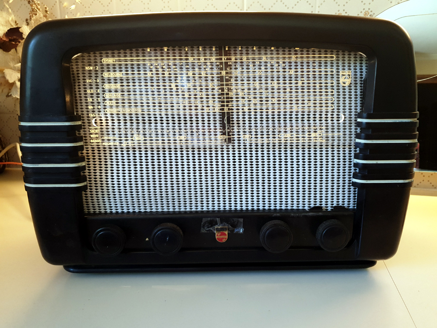 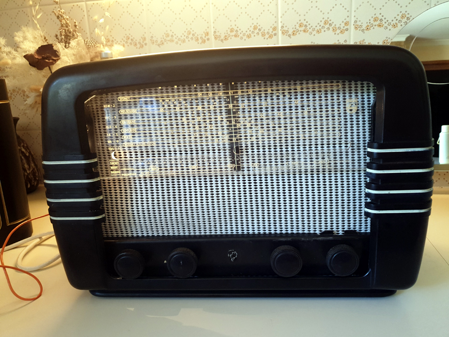   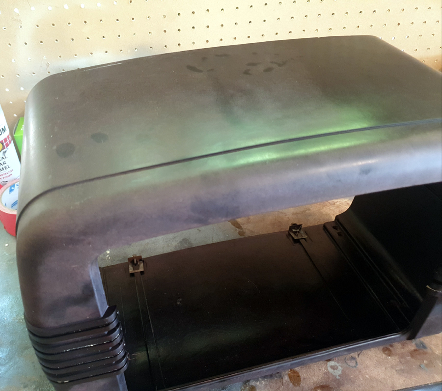 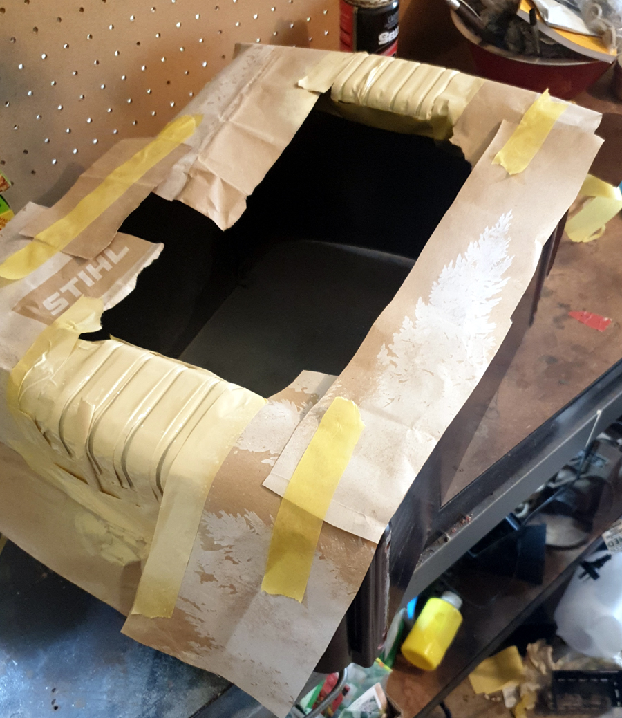 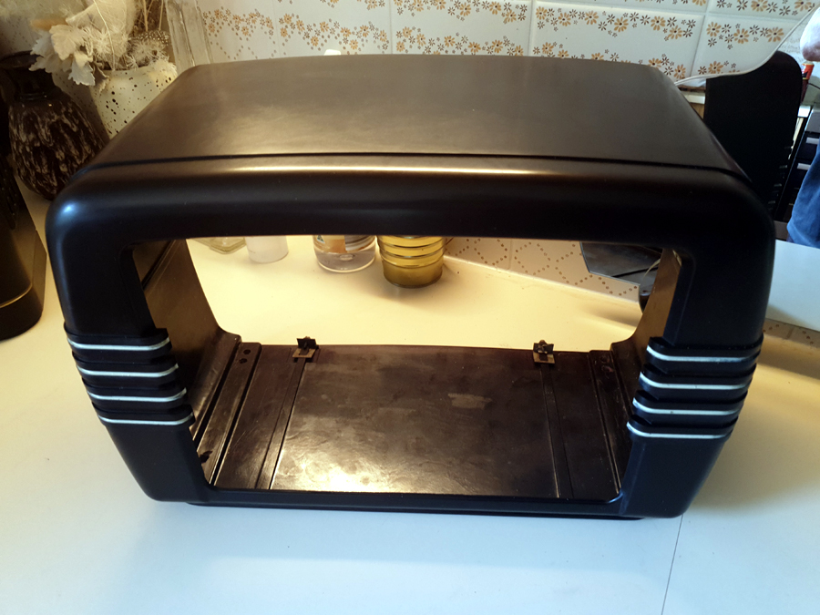 |
|
|
Return to top of page · Post #: 23 · Written at 4:24:47 PM on 13 December 2023.
|
|
|
|
Location: Wangaratta, VIC
Member since 21 February 2009 Member #: 438 Postcount: 5266 |
|
As pointed out on numerous occasions (add infinitum) a Signal Generator with a good waveform and not overloading the system; In conjunction with an oscilloscope. Is a formidable combination for finding the source of distortion. |
|
|
Return to top of page · Post #: 24 · Written at 7:32:49 PM on 16 December 2023.
|
|
|
|
Location: Latham, ACT
Member since 21 February 2015 Member #: 1705 Postcount: 2158 |
|
Photos sent |
|
|
Return to top of page · Post #: 25 · Written at 4:48:10 AM on 17 December 2023.
|
|

|
Administrator
Location: Naremburn, NSW
Member since 15 November 2005 Member #: 1 Postcount: 7311 |
|
Photos uploaded. Apologies for the delay, I've just returned from a camping trip. ‾‾‾‾‾‾‾‾‾‾‾‾‾‾‾‾‾‾‾‾‾‾‾‾‾‾‾‾‾‾‾‾‾‾‾‾‾‾‾‾‾‾‾‾‾‾‾‾‾‾‾‾‾‾‾‾‾‾‾‾‾‾‾‾‾‾‾‾ A valve a day keeps the transistor away... |
|
|
Return to top of page · Post #: 26 · Written at 8:16:09 PM on 17 December 2023.
|
|
|
|
Location: Latham, ACT
Member since 21 February 2015 Member #: 1705 Postcount: 2158 |
|
Thankyou Brad Hope you enjoyed the camp. |
|
|
Return to top of page · Post #: 27 · Written at 8:40:33 PM on 18 December 2023.
|
|

|
Location: Hill Top, NSW
Member since 18 September 2015 Member #: 1801 Postcount: 2018 |
|
Now I can see the photo, I thought it looked familiar. I have a Mullard MAS1111 that looks the same, except that the 4 white dashes on the sides are a reddish-orange colour, and the dial glass is obviously different. The white patterning on the front is a different pattern too. |
|
|
Return to top of page · Post #: 28 · Written at 9:22:44 PM on 18 December 2023.
|
|
|
|
Location: Wangaratta, VIC
Member since 21 February 2009 Member #: 438 Postcount: 5266 |
|
That tube combination often with a different rectifier, was somewhat common in HMV as well. 6N8 can be a horror tube. However, despite it being a tube with a separate exciter, 6AN7 was rarely used outside Australia and was principally a broadcast band tube. |
|
|
Return to top of page · Post #: 29 · Written at 10:57:30 PM on 18 December 2023.
|
|
|
|
Location: Hill Top, NSW
Member since 18 September 2015 Member #: 1801 Postcount: 2018 |
|
Decided to try it out, in fact electrically it works fine, although a bit of jiggling of the band-switch is needed on shortwave or it cuts out. |
|
|
Return to top of page · Post #: 30 · Written at 7:11:18 AM on 19 December 2023.
|
|
|
|
Location: Latham, ACT
Member since 21 February 2015 Member #: 1705 Postcount: 2158 |
|
ROBBERT |
|
|
You need to be a member to post comments on this forum.
|
|
Sign In
Vintage Radio and Television is proudly brought to you by an era where things were built with pride and made to last.
DISCLAIMER: Valve radios and televisions contain voltages that can deliver lethal shocks. You should not attempt to work on a valve radio or other electrical appliances unless you know exactly what you are doing and have gained some experience with electronics and working around high voltages. The owner, administrators and staff of Vintage Radio & Television will accept no liability for any damage, injury or loss of life that comes as a result of your use or mis-use of information on this website. Please read our Safety Warning before using this website.
WARNING: Under no circumstances should you ever apply power to a vintage radio, television or other electrical appliance you have acquired without first having it checked and serviced by an experienced person. Also, at no time should any appliance be connected to an electricity supply if the power cord is damaged. If in doubt, do not apply power.
Shintara - Keepin' It Real · VileSilencer - Maintain The Rage