
Tech Talk
Forum home - Go back to Tech talk
|
Help needed to identify a B&W TV Chassis
|
|
|
Return to top of page · Post #: 1 · Written at 9:05:52 PM on 14 December 2021.
|
|
|
|
Location: Melbourne, VIC
Member since 26 December 2010 Member #: 794 Postcount: 401 |
|
Hi everyone 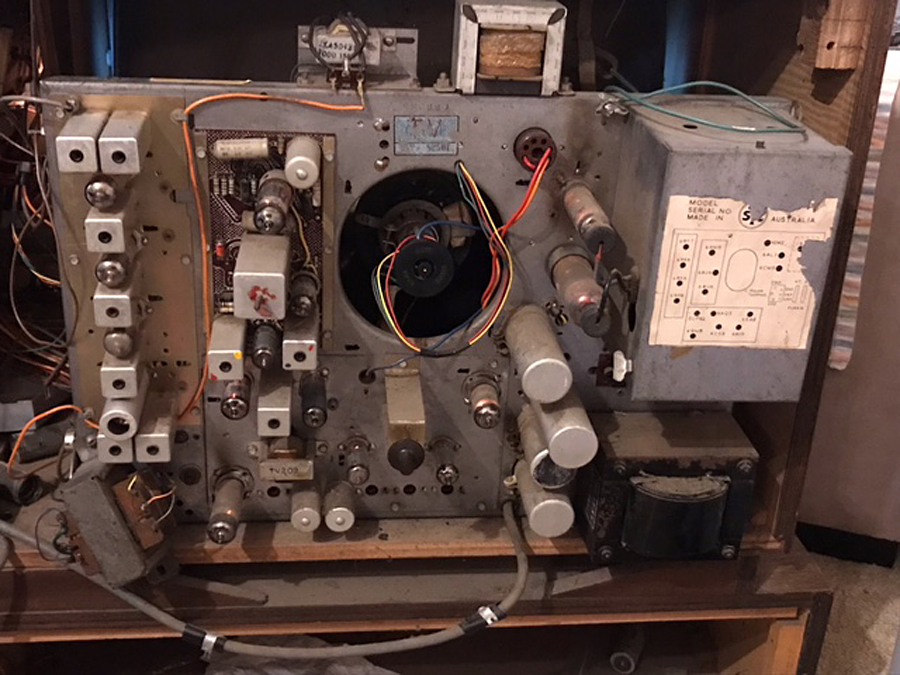 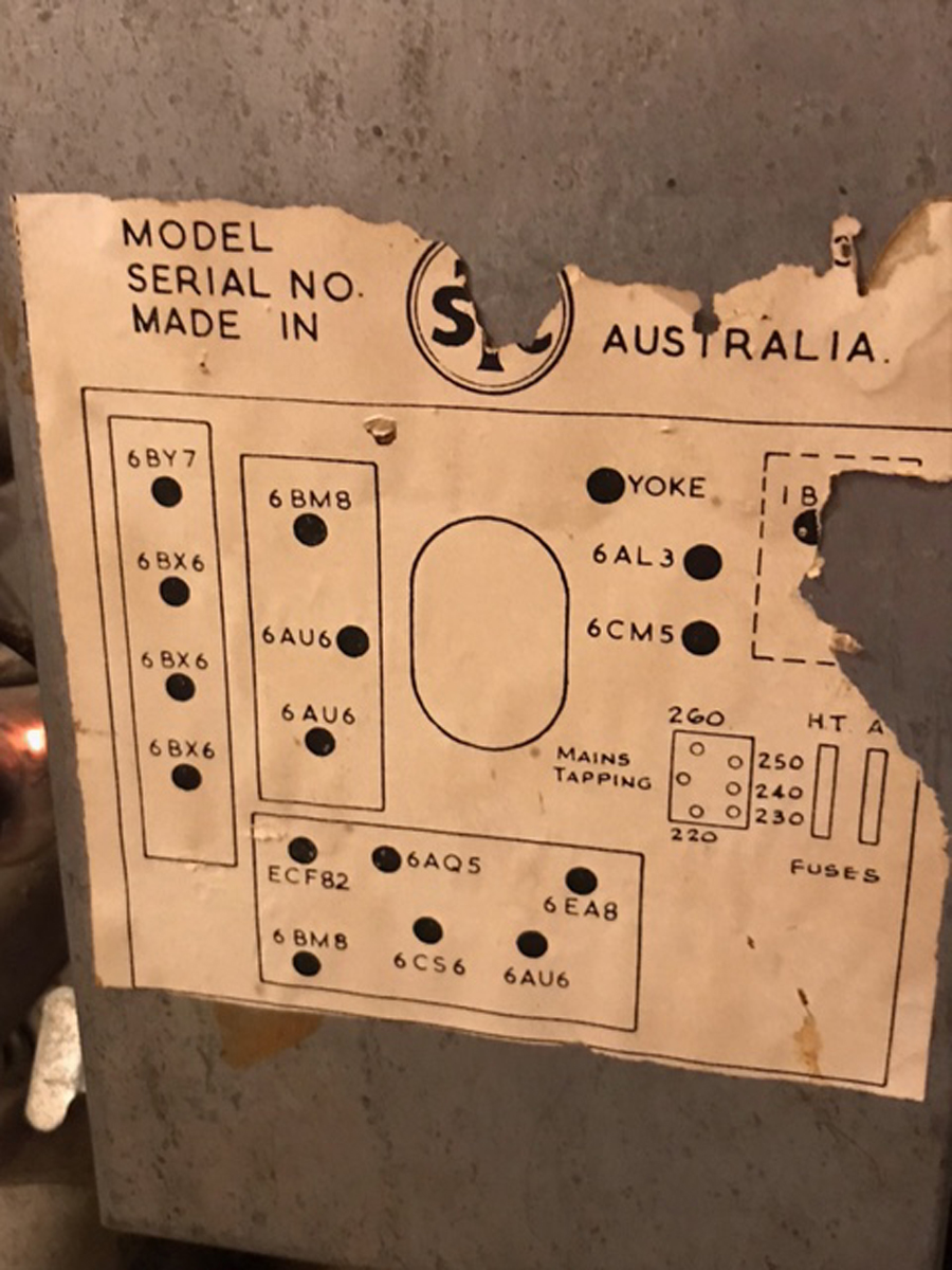 |
|
|
Return to top of page · Post #: 2 · Written at 11:55:08 PM on 14 December 2021.
|
|

|
Location: Wangaratta, VIC
Member since 21 February 2009 Member #: 438 Postcount: 5715 |
|
The old tele's are very much like an oscilloscope but in most cases took their synchronisation from the 50Hz mains. As it lead & lagged often pictures started to roll. This was always exacerbated by poor quality valves going out of spec. & a major contribution was made by wax paper caps leaking. This problem will be likely improved substantially by getting rid of all wax paper caps & old electrolytic caps and overhauling the synchronisation circuits. |
|
|
Return to top of page · Post #: 3 · Written at 9:06:29 PM on 15 December 2021.
|
|

|
Administrator
Location: Naremburn, NSW
Member since 15 November 2005 Member #: 1 Postcount: 7624 |
|
Photos uploaded. ‾‾‾‾‾‾‾‾‾‾‾‾‾‾‾‾‾‾‾‾‾‾‾‾‾‾‾‾‾‾‾‾‾‾‾‾‾‾‾‾‾‾‾‾‾‾‾‾‾‾‾‾‾‾‾‾‾‾‾‾‾‾‾‾‾‾‾‾ A valve a day keeps the transistor away... |
|
|
Return to top of page · Post #: 4 · Written at 10:21:53 PM on 15 December 2021.
|
|

|
Location: Hill Top, NSW
Member since 18 September 2015 Member #: 1801 Postcount: 2254 |
|
With that valve line-up, I'm guessing later 1960s - even though there's a printed circuit board. Newer sets would more likely use valves such as 6EH7, 6GV8, 6DQ6A etc. |
|
|
Return to top of page · Post #: 5 · Written at 10:08:27 AM on 16 December 2021.
|
|
|
|
Location: Wangaratta, VIC
Member since 21 February 2009 Member #: 438 Postcount: 5715 |
|
The chassis has a serial number. That may be useful & often transformers and speakers had a date on them. As that lower left transformer shows no likely hood of belonging on the top of the chassis; Its possibly a sub. |
|
|
Return to top of page · Post #: 6 · Written at 8:52:37 PM on 16 December 2021.
|
|
|
|
Location: Toongabbie, NSW
Member since 19 November 2015 Member #: 1828 Postcount: 1407 |
|
My JR field service manual (1971) stops at model T236 (730 SU-11). |
|
|
Return to top of page · Post #: 7 · Written at 10:10:13 PM on 16 December 2021.
|
|
|
|
Location: Melbourne, VIC
Member since 26 December 2010 Member #: 794 Postcount: 401 |
|
Thanks Gents, I’ll be interested in what Ian says too |
|
|
Return to top of page · Post #: 8 · Written at 7:23:02 PM on 17 December 2021.
|
|
|
|
Location: Belrose, NSW
Member since 31 December 2015 Member #: 1844 Postcount: 2710 |
|
That is an STC T236, the rare fringe chassis. Dates from 1961. |
|
|
Return to top of page · Post #: 9 · Written at 7:30:31 PM on 17 December 2021.
|
|
|
|
Location: Belrose, NSW
Member since 31 December 2015 Member #: 1844 Postcount: 2710 |
|
No TV in Australia EVER took synchronization from the mains. |
|
|
Return to top of page · Post #: 10 · Written at 7:18:09 AM on 18 December 2021.
|
|
|
|
Location: Toongabbie, NSW
Member since 19 November 2015 Member #: 1828 Postcount: 1407 |
|
Agree with Ian! |
|
|
Return to top of page · Post #: 11 · Written at 12:28:45 PM on 18 December 2021.
|
|

|
Location: Melbourne, VIC
Member since 20 September 2011 Member #: 1009 Postcount: 1263 |
|
The full service manual for the STC T236 is here: |
|
|
Return to top of page · Post #: 12 · Written at 2:10:05 PM on 18 December 2021.
|
|
|
|
Location: Melbourne, VIC
Member since 26 December 2010 Member #: 794 Postcount: 401 |
|
Thanks Gents. Kevin sent me the service manual yesterday too. |
|
|
Return to top of page · Post #: 13 · Written at 2:12:05 PM on 18 December 2021.
|
|
|
|
Location: Wangaratta, VIC
Member since 21 February 2009 Member #: 438 Postcount: 5715 |
|
They were always interesting the mains did affect them & the synchronization was always unstable. as soon as meal times came around and the voltage changed off it would wander, lots were the same. no sooner had you sorted it, off would come the peak load and the Horizontal would start rolling, |
|
|
Return to top of page · Post #: 14 · Written at 3:11:03 PM on 18 December 2021.
|
|

|
Location: Hobart, TAS
Member since 31 July 2016 Member #: 1959 Postcount: 605 |
|
You must have had a faulty set Marc. |
|
|
Return to top of page · Post #: 15 · Written at 3:59:41 PM on 18 December 2021.
|
|
|
|
Location: Hobart, TAS
Member since 31 July 2016 Member #: 1959 Postcount: 605 |
|
Another thought, poor reception etc could cause the sync separator circuit to try and latch on to anything, including mains hum. |
|
|
You need to be a member to post comments on this forum.
|
|
Sign In
Vintage Radio and Television is proudly brought to you by an era where things were built with pride and made to last.
DISCLAIMER: Valve radios and televisions contain voltages that can deliver lethal shocks. You should not attempt to work on a valve radio or other electrical appliances unless you know exactly what you are doing and have gained some experience with electronics and working around high voltages. The owner, administrators and staff of Vintage Radio & Television will accept no liability for any damage, injury or loss of life that comes as a result of your use or mis-use of information on this website. Please read our Safety Warning before using this website.
WARNING: Under no circumstances should you ever apply power to a vintage radio, television or other electrical appliance you have acquired without first having it checked and serviced by an experienced person. Also, at no time should any appliance be connected to an electricity supply if the power cord is damaged. If in doubt, do not apply power.
Shintara - Keepin' It Real · VileSilencer - Maintain The Rage