
Tech Talk
Forum home - Go back to Tech talk
|
Help needed to identify a B&W TV Chassis
|
|
|
Return to top of page · Post #: 16 · Written at 7:53:32 PM on 18 December 2021.
|
|

|
Location: Wangaratta, VIC
Member since 21 February 2009 Member #: 438 Postcount: 5257 |
|
Not the TV that behaviour was quite common. It did not matter if it was city or out of town. Some were just unstable. It is actually incredible how much RF rides on the power supply aerials around here. The are quite a few filters on lines here to get rid of it. Worst reception here is Mobile phones. Mine struggles as the signal is coming from 40km away. |
|
|
Return to top of page · Post #: 17 · Written at 8:55:24 AM on 20 December 2021.
|
|
|
|
Location: Melbourne, VIC
Member since 26 December 2010 Member #: 794 Postcount: 387 |
|
Thanks for all your help thus far, any suggestions on the flaking Aquadag on the back of the picture tube? |
|
|
Return to top of page · Post #: 18 · Written at 11:06:46 AM on 20 December 2021.
|
|

|
Location: Hobart, TAS
Member since 31 July 2016 Member #: 1959 Postcount: 544 |
|
If the Aquadag, is mostly intact then just leave it. |
|
|
Return to top of page · Post #: 19 · Written at 4:34:14 PM on 20 December 2021.
|
|
|
|
Location: Belrose, NSW
Member since 31 December 2015 Member #: 1844 Postcount: 2372 |
|
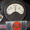
Here you go: |
|
|
Return to top of page · Post #: 20 · Written at 5:32:38 AM on 21 December 2021.
|
|
|
Location: Silver City WI, US
Member since 10 May 2013 Member #: 1340 Postcount: 977 |
|
It even has DC restoration, definitely a deluxe chassis. |
|
|
Return to top of page · Post #: 21 · Written at 10:18:18 PM on 21 December 2021.
|
|
|
|
Location: Belrose, NSW
Member since 31 December 2015 Member #: 1844 Postcount: 2372 |
|
Others have been asking about aquadag: |
|
|
Return to top of page · Post #: 22 · Written at 2:22:59 AM on 22 December 2021.
|
|
|
|
Location: Silver City WI, US
Member since 10 May 2013 Member #: 1340 Postcount: 977 |
|
These STCs had a big wire-wound pot for contrast in the cathode of their 6AQ5 odd choice for a video output stage. These would become noisy but were sealed, the trick was to peal back some of its metal cover to spray it. |
|
|
Return to top of page · Post #: 23 · Written at 8:25:18 AM on 22 December 2021.
|
|
|
|
Location: Toongabbie, NSW
Member since 19 November 2015 Member #: 1828 Postcount: 1251 |
|
Hi New Vista, that mention of a WW pot reminded me I did the same in my 2017 3" TV. |
|
|
Return to top of page · Post #: 24 · Written at 11:35:29 PM on 22 December 2021.
|
|
|
|
Location: Silver City WI, US
Member since 10 May 2013 Member #: 1340 Postcount: 977 |
|
I meant to say using a 6AQ5 seemed the odd choice, not so much the cathode contrast control. |
|
|
Return to top of page · Post #: 25 · Written at 7:04:08 AM on 23 December 2021.
|
|
|
|
Location: Toongabbie, NSW
Member since 19 November 2015 Member #: 1828 Postcount: 1251 |
|
Ah yes I agree, I guess they had a warehouse full of 6AQ5 for radios and stuff and just needed a couple of watts of pentode to do the job so in it went. A production choice. |
|
|
Return to top of page · Post #: 26 · Written at 7:09:26 PM on 28 December 2021.
|
|
|
|
Location: Melbourne, VIC
Member since 26 December 2010 Member #: 794 Postcount: 387 |
|
Thanks for your help. |
|
|
You need to be a member to post comments on this forum.
|
|
Sign In
Vintage Radio and Television is proudly brought to you by an era where things were built with pride and made to last.
DISCLAIMER: Valve radios and televisions contain voltages that can deliver lethal shocks. You should not attempt to work on a valve radio or other electrical appliances unless you know exactly what you are doing and have gained some experience with electronics and working around high voltages. The owner, administrators and staff of Vintage Radio & Television will accept no liability for any damage, injury or loss of life that comes as a result of your use or mis-use of information on this website. Please read our Safety Warning before using this website.
WARNING: Under no circumstances should you ever apply power to a vintage radio, television or other electrical appliance you have acquired without first having it checked and serviced by an experienced person. Also, at no time should any appliance be connected to an electricity supply if the power cord is damaged. If in doubt, do not apply power.
Shintara - Keepin' It Real · VileSilencer - Maintain The Rage