Welcome to Australia's only Vintage Radio and Television discussion forums. You are not logged in. Please log in below, apply for an account or retrieve your password.
Australian Vintage Radio Forums
  Home  ·  About Us  ·  Discussion Forums  ·  Glossary  ·  Outside Links  ·  Policies  ·  Services Directory  ·  Safety Warnings  ·  Tutorials

Tech Talk

Forum home - Go back to Tech talk

 STC 5031
« Back · 1 · 2 · Next »
 Return to top of page · Post #: 1 · Written at 9:21:15 AM on 13 July 2010.
Sandbar40's Gravatar
 Location: Tauranga, NZ
 Member since 13 July 2010
 Member #: 695
 Postcount: 35

My first post is a request for schematic alignment procedure etc. for an stc upright table model.
Label reads, CODE 5031 No 1024.
It is a 3 band with 5Z4 6A8 6K7 6K7 6B8 6F6.
Has A1 A2 and Pick Up terminals.
Most components are mounted on 2 large tag strips, there is a ww voltage divider and ww pot.
Any help much appreciated.


 Return to top of page · Post #: 2 · Written at 10:23:51 AM on 14 July 2010.
STC830's Gravatar
 Location: NSW
 Member since 10 June 2010
 Member #: 681
 Postcount: 1265

Hello sandbar40

According to

http://www.southcom.com.au/~pauledgr/STC.htm (Find Out How Old Your STC Radio Is link at the bottom)

the 5031 was never released on the market (actually withdrawn before production) so it may well be very rare. Perhaps it was bought by an employee or escaped over the back fence of the factory.

If not released however it is curious that it has a serial number of 1024.

According to the footnote it is similar to the 5035K a 1937 AC triplewave. This would appear to indicate that it is a 1937 radio, so yours should have a letter prefix of D on the blue ARTS&P sticker if it has survived.

But this list indicates that the circuit is not in AORSM (circuit book) for 1937 so it may be assumed to be similar to the 1938 triplewaves. The trouble is the most likely is the 630, but this has valve line-up 6U7, 6A8, 6U7, 6B8, 6F6, 5Z4, and a 6T5 magic eye.
This might be it if the 6K7 is equivalent to the 6U7 and yours also has a magic eye visible through the dial.

Is the 5031 stamped on the chassis at the back as well as on the STC lable?

Be aware that if the power cord has a bakelite plug & socket this is used to adjust for the line voltage. It should have the 240 up. Get it upside down & there will be smoke!!

Finally I have seen errors in the STC document, so getting the age from the ARTS&P sticker should be the touchstone.

An interesting puzzle!!

Can you send Brad a picture to post?

Cheers
Graham


 Return to top of page · Post #: 3 · Written at 3:34:34 PM on 14 July 2010.
Sandbar40's Gravatar
 Location: Tauranga, NZ
 Member since 13 July 2010
 Member #: 695
 Postcount: 35

Hi Graham,

Thanks for your research.
There is no magic eye or provision for one.
A & P sticker does indeed have a D followed by 21161.
Above the A&P sticker is another, reading, 'Patent licence extended for use in the Dominion of New Zealand'.
The no. 1024 is the only no. stamped into the chassis.
The valve line up I quoted is also on the paper sticker on the back of the chassis.
Two of the voltage pins have been bent down, so no risk of wrong connection.

Will get some photos shortly.

I'll continue to update repair progress- with some help I expect.

Regards,


Tim.

STC 5031 Table Radio
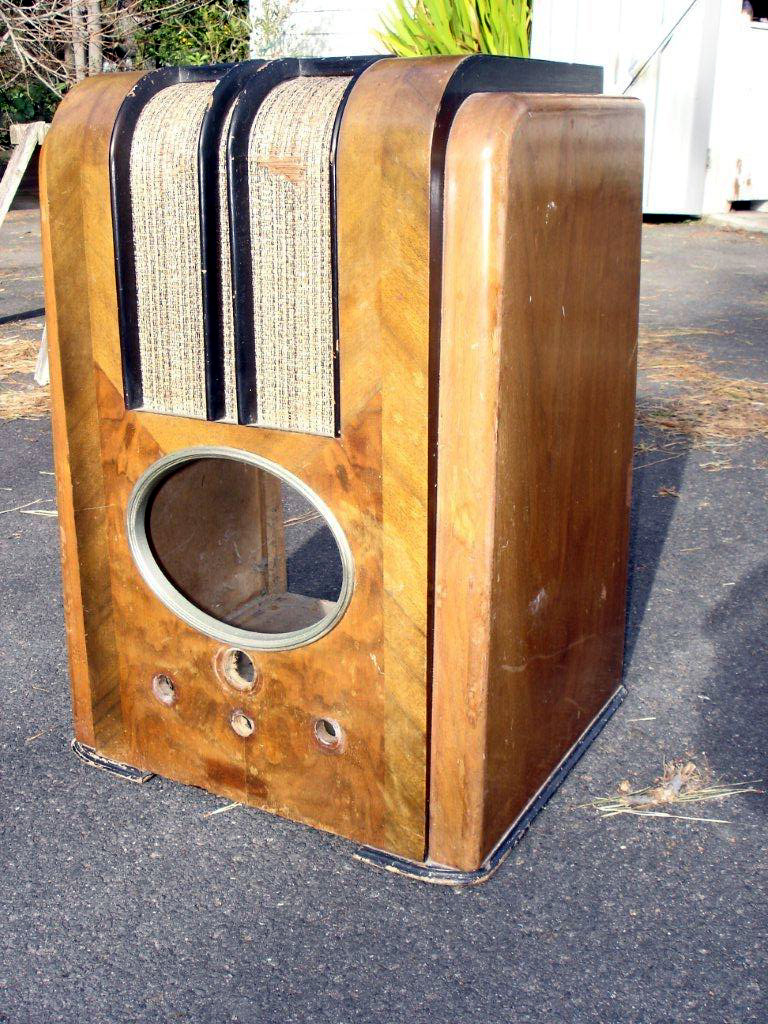
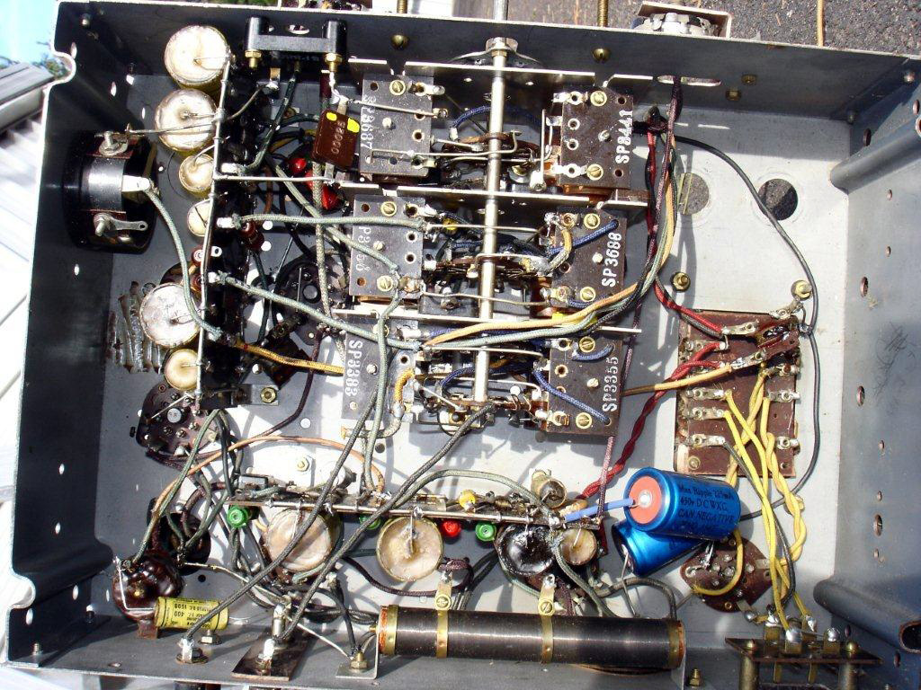
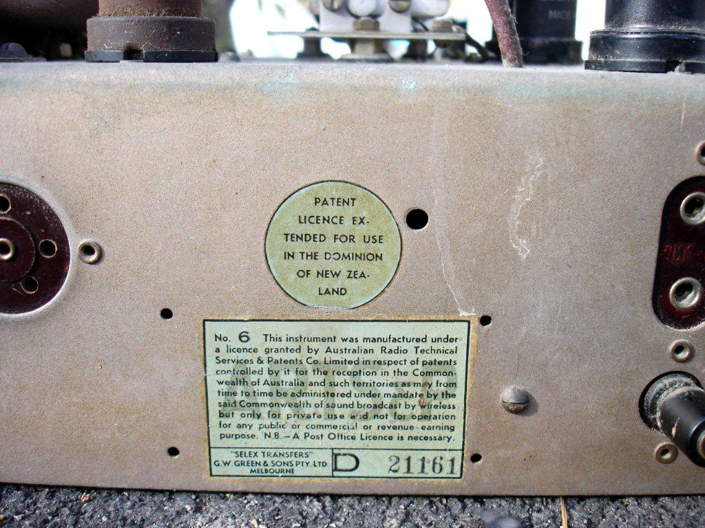
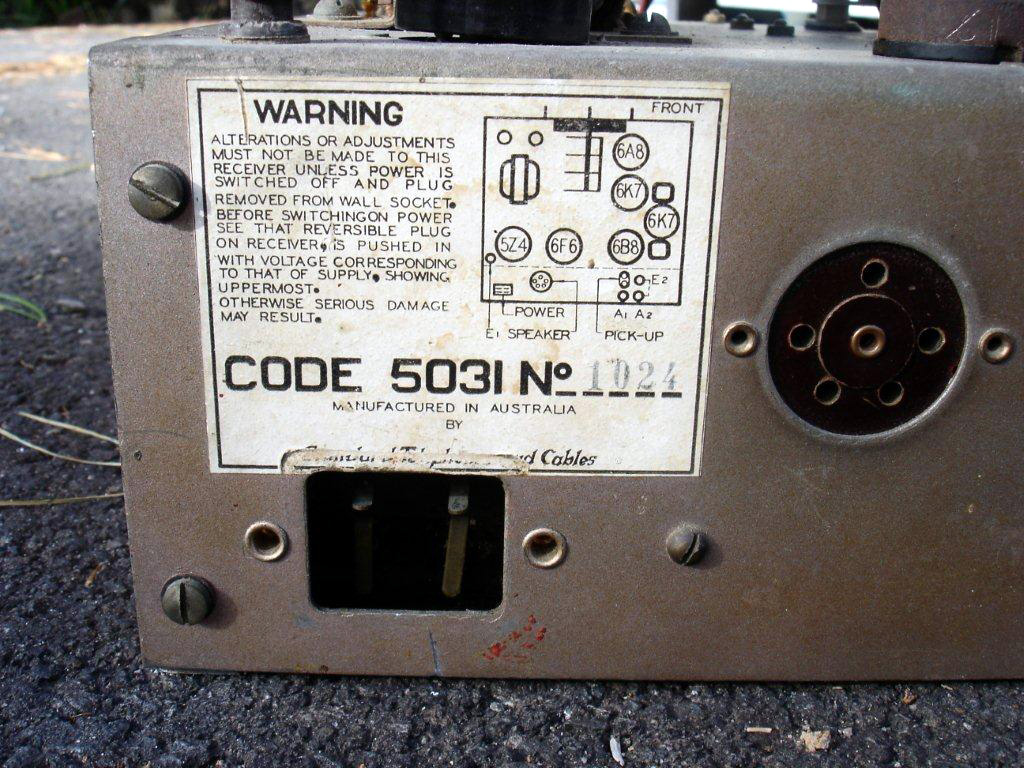
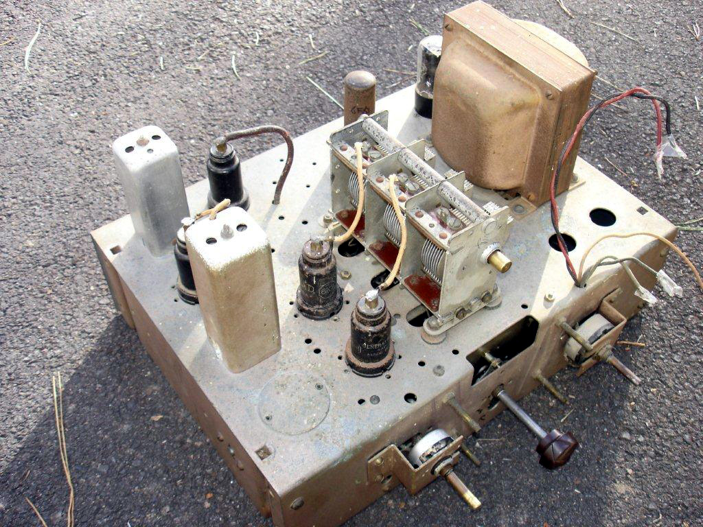
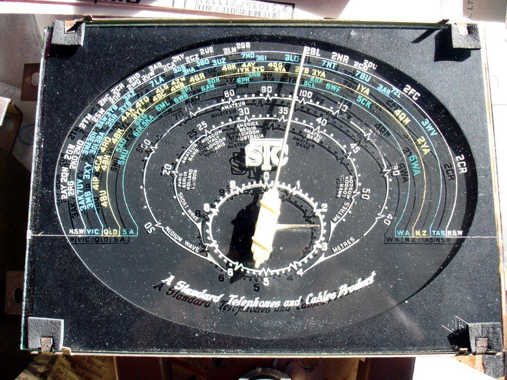
Click on image for larger resolution


 Return to top of page · Post #: 4 · Written at 4:54:25 PM on 14 July 2010.
STC830's Gravatar
 Location: NSW
 Member since 10 June 2010
 Member #: 681
 Postcount: 1265

Hello again Tim

I have found my 1937 AORSM in the garage and it has a circuit for a 5031.
But the valve line-up is 6D6 6A7 6D6 6B7 42 280 with a 6G5 indicator valve. It is an AC triple wave.

There is no 5035K in 1937 or 1938.

The plot thickens

Graham

PS according to http://www.r-type.org/exhib/aaa0353.htm
the 6K7 was an IF amplifier so would have done the same job as a 6U7


 Return to top of page · Post #: 5 · Written at 8:43:29 PM on 14 July 2010.
Marcc's avatar
 Location: Wangaratta, VIC
 Member since 21 February 2009
 Member #: 438
 Postcount: 5269

If my memory serves me well. 6D6 is a 6U7 with a different base. 6A7, 6A8 same deal. 6B7, 6B8 again base different only; 42 became 6F6 when they changed the base.

6U7 is slightly different to 6K7 albeit they are both super control amps and have the same pinouts. I have seen one work in the place of the other.

Marc


 Return to top of page · Post #: 6 · Written at 5:04:57 PM on 15 July 2010.
STC830's Gravatar
 Location: NSW
 Member since 10 June 2010
 Member #: 681
 Postcount: 1265

Thanks Marcc, I didn't mean to hint that the 6K7 and 6U7 were identical in characteristics. Just that the 6K7 was the right valve for the job.

If the radio was withdrawn after manufacture of at least 1024 examples, one wonders why:
- a design flaw?
- a manufacturing error?

If this is the case then this radio might have modifications from the original.

For example a fatal manufacturing fault might be an error in the mains transformer winding, and the existing transformer may not be the original. Worth looking out for this sort of thing

Out of interest a link to a story on the 5030
http://vintagewireless.byethost12.com/stc.html

Graham


 Return to top of page · Post #: 7 · Written at 9:02:18 PM on 15 July 2010.
Marcc's avatar
 Location: Wangaratta, VIC
 Member since 21 February 2009
 Member #: 438
 Postcount: 5269

Mainly pointing out that a 6U7 in the place of 6K7 may not end badly.

There were often Proto types & specials for the bosses let loose. I recently had a horror AWA that was a variant based on an 301A.

In every couple of hundred, or so radio's you seem to win one or two like this.

The 301 had an optional Type 686 push pull amp with 42's& its own power supply. 301A output was a single 42.

I ended up drawing a circuit specifically of the variant, due to significant variations. Essentially the circuit had similarity but...
Variant had a sensitivity control and needed it.301A did not.
Variant's (1st IF Bandpass filter on both) IF was 455kHz not the same as 301A
Monkey had messed up the AGC. It was meant to be delayed resistors were different (factory) than 301A
Variant had a Cathode resistor to tame the 42 now used as PP driver. Listed in parts correctly.
Cathode resistors in most cases different as Variant had 6A6 (Class C Double Triode.....1 cathode) PP built on chassis.
Feild moved from B+ to B-. Choke as used in 686 added to B+, extra filter cap added. All large paper 8μF. Fidler messed up here.
Replacement 10μF Sprauge Atoms. One on field positive to cathode, Negative to CT (trap & fildler fell for it). This is why cathode resistors are different ...... bias change. A301had back bias

The speaker was 10Kg I wonder if they matched the moments of its inertia with the power? Horseshoe of the magnet was 3/4" x 2" Flat.

After all of that...... This set would be one of the quietest (no power supply noise) most sensitive & selective sets that I have worked on. It still puts to shame, many sets that came after it. It is apparent that no expense was spared getting this thing right.

Most of the drama with this set was caused by the fidler & no correct information to indicate what was different. This was in no way helped by the fidler altering / breaking the bandpass filter & throwing the entire IF and the four sets of RF coils off frequency, probably in a futile attempt to get it working.
3 Band with pre amps. A301 7 Valve Variant 8

Marc


 Return to top of page · Post #: 8 · Written at 10:01:57 PM on 15 July 2010.
STC830's Gravatar
 Location: NSW
 Member since 10 June 2010
 Member #: 681
 Postcount: 1265

Yes - the possibilities are endless.

I had smaller problems with my STC830.
The voltage divider had burnt out and was replaced with a non-standard circuit. I would still like to know the original total resistance of this wire wound resistor. That said I assumed a total of 20K and played around until the voltages looked right.

This was caused by my grandfather when, according to legend, he plugged the power cord plug in the wrong way and fritzed a few components - hence my warning above.

---------------

when search
http://www.hws.org.au/RadioHistory/manufacturers/STC.htm
for 6K7 there are no hits so did not figure in any official valve line-up.
--------------------------------
Here is the 5035K - it has an eye, as has the 5031 in AORSM.

http://newspapers.nla.gov.au/ndp/del/article/17396807?searchTerm=stc+radio+1937

SMH Saturday 6 November 1937, p20
--------

Tim I will send the 5031 circuit if you like.

Graham


 Return to top of page · Post #: 9 · Written at 12:53:02 AM on 16 July 2010.
Marcc's avatar
 Location: Wangaratta, VIC
 Member since 21 February 2009
 Member #: 438
 Postcount: 5269

Midwest USA was using the octals in 1934. So they were about.

It could be that a 5030H, which had all of the equivalent valves was fitted with the identical octals needing only socket changes. and the addition of an RF stage ahead of the converter. 6K7 may have proved a problem as 6U7 tends to have been the common one made here.

5Z4 was a slower heating rectifier as it has a cathode, albeit tied to the filament on pin8.

Much speculation

Marc


 Return to top of page · Post #: 10 · Written at 9:55:51 AM on 16 July 2010.
STC830's Gravatar
 Location: NSW
 Member since 10 June 2010
 Member #: 681
 Postcount: 1265

Since the radio is in New Zealand and NZ imported a lot of US radios, maybe 6K7s were available there.

re 5Z4 important not to use a directly heated cathode eg 5Y3 rectifier as this would result in a rapid voltage build up before the other valves cathodes have heated up and able to draw current. Evidently reduces voltage stress on components especially large electrolytics - its a while since I read this hint so I might have it wrong.

Graham


 Return to top of page · Post #: 11 · Written at 1:06:01 PM on 16 July 2010.
Marcc's avatar
 Location: Wangaratta, VIC
 Member since 21 February 2009
 Member #: 438
 Postcount: 5269

I must re visit the spec sheet of the two RF pentodes. The yanks seemed to use a lot of 6K7's & 6U7 was a horror without shields and not spectacular in the reliabiliy area. I have had to replace quite a few.

The slower thermal inertia 5Z4 Rectifier does reduce the surge. The Sovtek 5Y3 is built like the later rectifiers eg. 6X4 Rather than an air conditioner duct with a heater in it.

A much more robust design with a large tubular filament, more like a 6x4 etc only larger in diameter. This filament has an extremely high thermal inertia, which like 5Z4 results in a small surge (last one I measured, 25V above 250V B+) which takes considerable stress off components.

Marc


 Return to top of page · Post #: 12 · Written at 2:12:56 PM on 16 July 2010.
Sandbar40's Gravatar
 Location: Tauranga, NZ
 Member since 13 July 2010
 Member #: 695
 Postcount: 35

Thanks for your input guys,have some photos now , will send to Brad.

Graham - yes circuit would be appreciated. Someone has made some changes.

The 5031 has all metal valves except for rectifier, saving on shields?

Cabinet was made in NZ ( label inside )
Chassis has many 'spare' holes.


 Return to top of page · Post #: 13 · Written at 3:20:29 PM on 16 July 2010.
STC830's Gravatar
 Location: NSW
 Member since 10 June 2010
 Member #: 681
 Postcount: 1265

OK Tim I will get it scanned.

Do you want me send it to Brad to post or will you open up your email (show email form)? This can be done in such a way as to make it invisible to the sender. You can hide again once the message gets through.

See new email policy on home page

Graham


 Return to top of page · Post #: 14 · Written at 4:35:09 PM on 16 July 2010.
Sandbar40's Gravatar
 Location: Tauranga, NZ
 Member since 13 July 2010
 Member #: 695
 Postcount: 35

Graham,

e mail should be accessible now from profile.

Tim


 Return to top of page · Post #: 15 · Written at 4:45:09 PM on 16 July 2010.
STC830's Gravatar
 Location: NSW
 Member since 10 June 2010
 Member #: 681
 Postcount: 1265

OK Tim, done.


« Back · 1 · 2 · Next »
 You need to be a member to post comments on this forum.

Sign In

Username:
Password:
 Keep me logged in.
Do not tick box on a computer with public access.