
Tech Talk
Forum home - Go back to Tech talk
|
AWA EMPIRE STATE RADIO
|
|
|
Return to top of page · Post #: 1 · Written at 5:25:40 PM on 7 September 2020.
|
|
|
|
Location: Kanahooka, NSW
Member since 18 November 2016 Member #: 2012 Postcount: 712 |
|
Hello all. |
|
|
Return to top of page · Post #: 2 · Written at 6:46:40 PM on 7 September 2020.
|
|
|
|
Location: Belrose, NSW
Member since 31 December 2015 Member #: 1844 Postcount: 2713 |
|
Jim since you are going permag you will need to drop the excess 50 or 100 volts that was allocated to the field coil across a resistor, say 1.5k |
|
|
Return to top of page · Post #: 3 · Written at 7:50:40 PM on 7 September 2020.
|
|
|
|
Location: Kanahooka, NSW
Member since 18 November 2016 Member #: 2012 Postcount: 712 |
|
Hello Ian. 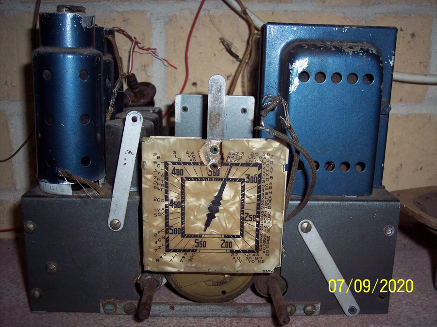 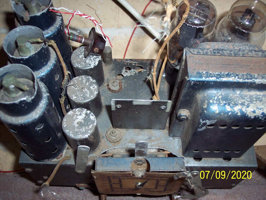 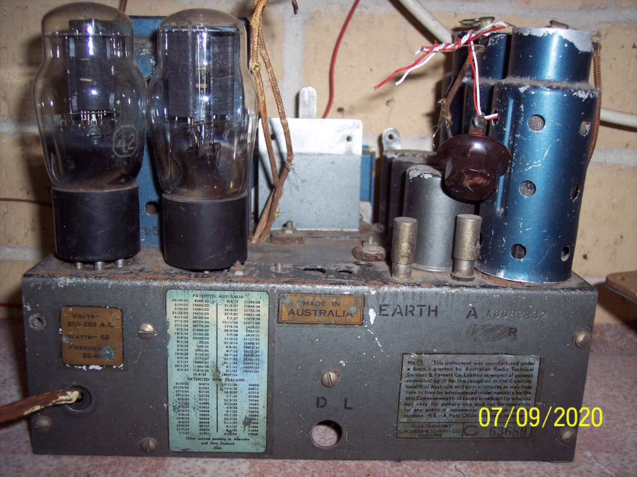 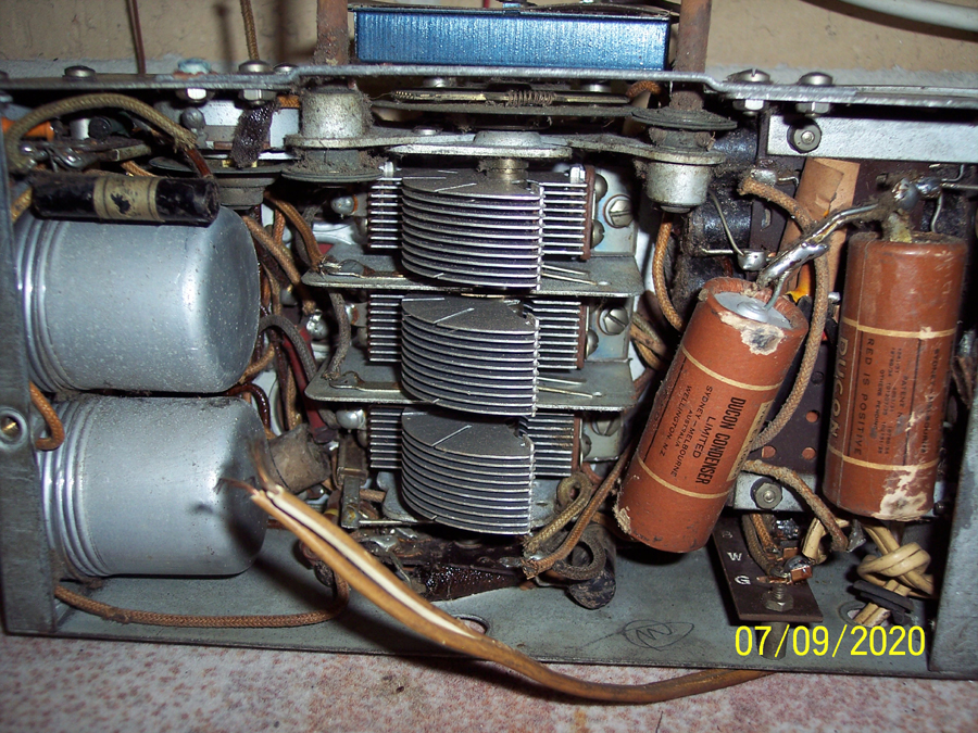 |
|
|
Return to top of page · Post #: 4 · Written at 8:09:50 PM on 7 September 2020.
|
|

|
Location: Wangaratta, VIC
Member since 21 February 2009 Member #: 438 Postcount: 5730 |
|
If you do go for resistance, which the circuit, or data sheet should tell you, current squared by resistance should give you an idea of the heat needed to be dissipated. I quite often use a panel mount type resistor, & RS components are one who has them. |
|
|
Return to top of page · Post #: 5 · Written at 9:34:34 PM on 7 September 2020.
|
|
|
|
Location: Kanahooka, NSW
Member since 18 November 2016 Member #: 2012 Postcount: 712 |
|
Thank you Marc. |
|
|
Return to top of page · Post #: 6 · Written at 10:12:13 PM on 7 September 2020.
|
|
|
|
Location: Kanahooka, NSW
Member since 18 November 2016 Member #: 2012 Postcount: 712 |
|
I now know why this looks incomplete. Because it is, there is supposed to be an asbestos sheet alongside the 80 rectifier and a rectangular metal can along side it . That is all missing, what is supposed to be in the can, was it filter capacitors ? It is going to be quite a task to turn this sow's ear into a silk purse. I can feel me getting cold feet it is certainly a long term project. |
|
|
Return to top of page · Post #: 7 · Written at 7:07:57 AM on 8 September 2020.
|
|
|
|
Location: Toongabbie, NSW
Member since 19 November 2015 Member #: 1828 Postcount: 1413 |
|
Hi Jimb, just take it a problem at a time. |
|
|
Return to top of page · Post #: 8 · Written at 8:14:31 AM on 8 September 2020.
|
|
|
|
Location: NSW
Member since 10 June 2010 Member #: 681 Postcount: 1408 |
|
I restored a Kriesler beehive in the late eighties using a metal clad ceramic resistor ratted from an old TV. It was mounted above the chassis to keep the heat as high up as possible. Only possible because this radio is totally enclosed in bakelite - wouldn't want such high voltage above the chassis if the back was open. |
|
|
Return to top of page · Post #: 9 · Written at 8:42:20 AM on 8 September 2020.
|
|
|
|
Location: Kanahooka, NSW
Member since 18 November 2016 Member #: 2012 Postcount: 712 |
|
Thanks Fred and STC 830. |
|
|
Return to top of page · Post #: 10 · Written at 10:15:58 AM on 8 September 2020.
|
|
|
|
Location: Wangaratta, VIC
Member since 21 February 2009 Member #: 438 Postcount: 5730 |
|
There are two principal filters. Where the rectifier valve is running close to its limit; We have the choke input filter, where there is no capacitor on the rectifier end. Then there is the capacitor input filter, where there is a capacitor on both ends. Designed properly, hum is not an issue. |
|
|
Return to top of page · Post #: 11 · Written at 11:52:04 AM on 8 September 2020.
|
|
|
|
Location: Kanahooka, NSW
Member since 18 November 2016 Member #: 2012 Postcount: 712 |
|
Thank you Marc. |
|
|
Return to top of page · Post #: 12 · Written at 11:56:26 AM on 8 September 2020.
|
|
|
|
Location: Belrose, NSW
Member since 31 December 2015 Member #: 1844 Postcount: 2713 |
|
Re the field coil and B+ current: |
|
|
Return to top of page · Post #: 13 · Written at 3:35:26 PM on 8 September 2020.
|
|
|
|
Location: Kanahooka, NSW
Member since 18 November 2016 Member #: 2012 Postcount: 712 |
|
Hello Ian, thank you for the information. I liked the look of that 1.5 k resistor I think I will order one it will bolt down somewhere with a good squirt of heat sink compound under it. Element 14 are such a Pain to deal with . Cannot see why they don't use PayPal. |
|
|
Return to top of page · Post #: 14 · Written at 5:01:51 PM on 8 September 2020.
|
|

|
Location: Hobart, TAS
Member since 31 July 2016 Member #: 1959 Postcount: 605 |
|
Jim, Just sent an email to you with some good info on the Empire. |
|
|
Return to top of page · Post #: 15 · Written at 5:43:20 PM on 8 September 2020.
|
|
|
|
Location: Kanahooka, NSW
Member since 18 November 2016 Member #: 2012 Postcount: 712 |
|
Thanks Johnny. |
|
|
You need to be a member to post comments on this forum.
|
|
 15 watts, assuming HT current of 100mA or less. This impedance will avoid the need for a choke, esp. if you increase the 2nd filter to say 16 or 22μF. The resistor could mount on the back of the square parts box tower or just about anywhere you can find space on the chassis:
Sign In
Vintage Radio and Television is proudly brought to you by an era where things were built with pride and made to last.
DISCLAIMER: Valve radios and televisions contain voltages that can deliver lethal shocks. You should not attempt to work on a valve radio or other electrical appliances unless you know exactly what you are doing and have gained some experience with electronics and working around high voltages. The owner, administrators and staff of Vintage Radio & Television will accept no liability for any damage, injury or loss of life that comes as a result of your use or mis-use of information on this website. Please read our Safety Warning before using this website.
WARNING: Under no circumstances should you ever apply power to a vintage radio, television or other electrical appliance you have acquired without first having it checked and serviced by an experienced person. Also, at no time should any appliance be connected to an electricity supply if the power cord is damaged. If in doubt, do not apply power.
Shintara - Keepin' It Real · VileSilencer - Maintain The Rage