
Tech Talk
Forum home - Go back to Tech talk
|
A little confused?
|
|
|
Return to top of page · Post #: 1 · Written at 4:54:12 PM on 29 August 2020.
|
|
|
|
Location: Bells Beach, VIC
Member since 20 July 2020 Member #: 2428 Postcount: 39 |
|
Hi there. 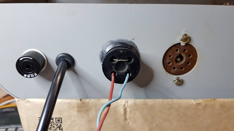 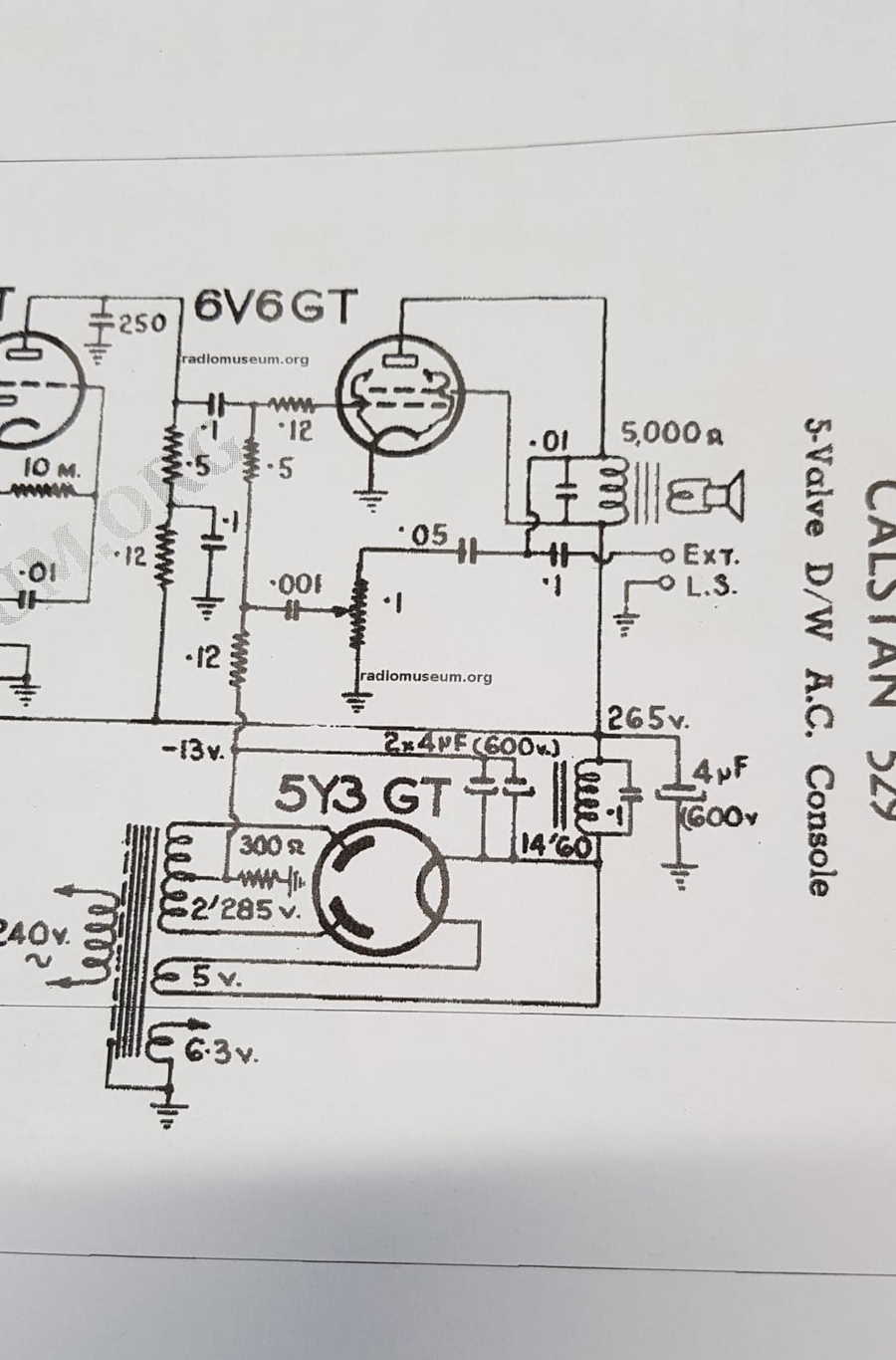 |
|
|
Return to top of page · Post #: 2 · Written at 6:17:43 PM on 29 August 2020.
|
|

|
Location: Sydney, NSW
Member since 28 January 2011 Member #: 823 Postcount: 6687 |
|
That arrangement was to remove B+ from the circuit in the event that the chassis was powered up while there was no speaker load attached. A safety measure to ensure that the output valve didn't run red in the face trying to work into a load of infinite impedance. |
|
|
Return to top of page · Post #: 3 · Written at 8:24:24 PM on 29 August 2020.
|
|

|
Administrator
Location: Naremburn, NSW
Member since 15 November 2005 Member #: 1 Postcount: 7302 |
|
Photos uploaded. ‾‾‾‾‾‾‾‾‾‾‾‾‾‾‾‾‾‾‾‾‾‾‾‾‾‾‾‾‾‾‾‾‾‾‾‾‾‾‾‾‾‾‾‾‾‾‾‾‾‾‾‾‾‾‾‾‾‾‾‾‾‾‾‾‾‾‾‾ A valve a day keeps the transistor away... |
|
|
Return to top of page · Post #: 4 · Written at 9:05:25 PM on 29 August 2020.
|
|
|
|
Location: Bells Beach, VIC
Member since 20 July 2020 Member #: 2428 Postcount: 39 |
|
GTC: Many thanks for that. That makes sense. |
|
|
Return to top of page · Post #: 5 · Written at 9:51:51 PM on 29 August 2020.
|
|

|
Location: Wangaratta, VIC
Member since 21 February 2009 Member #: 438 Postcount: 5254 |
|
Normally the early circuits were in Megohms on the 6V6 grid .5 (0.5) is 500K and check them, normally the grid resistors on 6V6 and the detector 1st audio plate are cactus. |
|
|
Return to top of page · Post #: 6 · Written at 9:59:27 PM on 29 August 2020.
|
|
|
|
Location: Sydney, NSW
Member since 28 January 2011 Member #: 823 Postcount: 6687 |
|
Possibly. Read the colour codes and go from there. |
|
|
Return to top of page · Post #: 7 · Written at 10:54:28 PM on 29 August 2020.
|
|
|
|
Location: Bells Beach, VIC
Member since 20 July 2020 Member #: 2428 Postcount: 39 |
|
Marcc: When you say the fuse is for decoration. Do you mean the one on the back panel. I've put that there on the active line as it enters the chassis. The 300 Ohm resistor is spot on in value. It is made up of two 150 ohm wire wound resistors in series. |
|
|
Return to top of page · Post #: 8 · Written at 11:05:44 PM on 29 August 2020.
|
|
|
|
Location: Sydney, NSW
Member since 28 January 2011 Member #: 823 Postcount: 6687 |
|
A number of the resistors do not seem to have any colours on them so I assume they have faded. |
|
|
Return to top of page · Post #: 9 · Written at 11:52:02 PM on 29 August 2020.
|
|
|
|
Location: Wangaratta, VIC
Member since 21 February 2009 Member #: 438 Postcount: 5254 |
|
The problem with a fuse in my experience when its on the primary side of the old transformer radios is, that tends to only protect that side it has to be a certain size, or in some cases slow blow to protect itself from inrush current and rarely if some thing goes awry on the secondary is it any more use than putting an ash tray on a Hogg. |
|
|
Return to top of page · Post #: 10 · Written at 1:36:50 AM on 30 August 2020.
|
|

|
Location: Hill Top, NSW
Member since 18 September 2015 Member #: 1801 Postcount: 2015 |
Yes. |
|
|
Return to top of page · Post #: 11 · Written at 11:39:36 AM on 30 August 2020.
|
|
|
|
Location: Bells Beach, VIC
Member since 20 July 2020 Member #: 2428 Postcount: 39 |
|
Marcc: I've asked Brad to post a photo showing the resistors. However I believe that they are original. Not sure I understand what you mean by resistors "sailing in the wind". 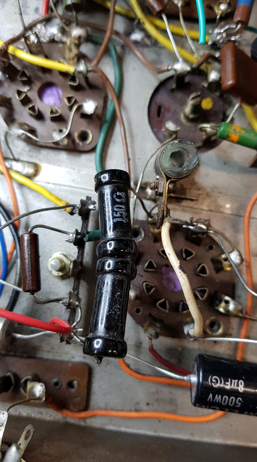 |
|
|
Return to top of page · Post #: 12 · Written at 12:09:36 AM on 31 August 2020.
|
|
|
|
Location: Wangaratta, VIC
Member since 21 February 2009 Member #: 438 Postcount: 5254 |
|
With resistors there is an important thing called, I (current) squared by R (resistance) = Watts. That tells you the wattage the resistor has to dissipate: Not the wattage of the resistor. The ramifications of this, is normally measured in smoke density. Viz if "W" exceeds the rating of the resistor it fry's. |
|
|
Return to top of page · Post #: 13 · Written at 5:33:36 AM on 31 August 2020.
|
|
|
|
Administrator
Location: Naremburn, NSW
Member since 15 November 2005 Member #: 1 Postcount: 7302 |
|
Photo uploaded to Post 11. ‾‾‾‾‾‾‾‾‾‾‾‾‾‾‾‾‾‾‾‾‾‾‾‾‾‾‾‾‾‾‾‾‾‾‾‾‾‾‾‾‾‾‾‾‾‾‾‾‾‾‾‾‾‾‾‾‾‾‾‾‾‾‾‾‾‾‾‾ A valve a day keeps the transistor away... |
|
|
Return to top of page · Post #: 14 · Written at 10:02:45 AM on 31 August 2020.
|
|
|
|
Location: Wangaratta, VIC
Member since 21 February 2009 Member #: 438 Postcount: 5254 |
|
Methinks that there has been a problem in that area that thing in a clamp looks like an accident. That black WW resistor type, I have seen in Japanese signal generators around the 60's but might date earlier. I suspect that they are far from original. Astor would be a brown one as in the pic. |
|
|
Return to top of page · Post #: 15 · Written at 11:47:46 AM on 31 August 2020.
|
|
|
|
Location: Melbourne, VIC
Member since 5 October 2009 Member #: 555 Postcount: 465 |
|
A question .... the 2 x 4μF electrolytic (??) caps in parallel on the Back Bias line in the circuit diagram ... are they orientated correctly?? ‾‾‾‾‾‾‾‾‾‾‾‾‾‾‾‾‾‾‾‾‾‾‾‾‾‾‾‾‾‾‾‾‾‾‾‾‾‾‾‾‾‾‾‾‾‾‾‾‾‾‾‾‾‾‾‾‾‾‾‾‾‾‾‾‾‾‾‾ Cheers, Ian |
|
|
You need to be a member to post comments on this forum.
|
|

Sign In
Vintage Radio and Television is proudly brought to you by an era where things were built with pride and made to last.
DISCLAIMER: Valve radios and televisions contain voltages that can deliver lethal shocks. You should not attempt to work on a valve radio or other electrical appliances unless you know exactly what you are doing and have gained some experience with electronics and working around high voltages. The owner, administrators and staff of Vintage Radio & Television will accept no liability for any damage, injury or loss of life that comes as a result of your use or mis-use of information on this website. Please read our Safety Warning before using this website.
WARNING: Under no circumstances should you ever apply power to a vintage radio, television or other electrical appliance you have acquired without first having it checked and serviced by an experienced person. Also, at no time should any appliance be connected to an electricity supply if the power cord is damaged. If in doubt, do not apply power.
Shintara - Keepin' It Real · VileSilencer - Maintain The Rage