
Tech Talk
Forum home - Go back to Tech talk
|
Astor Mickey OZ circuit variations over the production period, 1933 – 1935
|
|
|
Return to top of page · Post #: 31 · Written at 10:55:22 AM on 12 September 2018.
|
|

|
Location: Perth, WA
Member since 19 November 2008 Member #: 381 Postcount: 240 |
|
Excellent photos STC830. Now we need photos from a very early model with a serial number less than 3000, anyone? |
|
|
Return to top of page · Post #: 32 · Written at 4:10:29 PM on 12 September 2018.
|
|
|
|
Location: NSW
Member since 10 June 2010 Member #: 681 Postcount: 1407 |
|
"Slight accident..." |
|
|
Return to top of page · Post #: 33 · Written at 6:21:25 PM on 12 September 2018.
|
|

|
Administrator
Location: Naremburn, NSW
Member since 15 November 2005 Member #: 1 Postcount: 7624 |
|
Yeah, I am not sure how it all works with cut and paste sometimes. I've at times performed the "copy" part of the function from left to right, grabbing numerous files and then watched them be uploaded to the web server in a completely different order. It could be decided by file size or some other unknown aspect. ‾‾‾‾‾‾‾‾‾‾‾‾‾‾‾‾‾‾‾‾‾‾‾‾‾‾‾‾‾‾‾‾‾‾‾‾‾‾‾‾‾‾‾‾‾‾‾‾‾‾‾‾‾‾‾‾‾‾‾‾‾‾‾‾‾‾‾‾ A valve a day keeps the transistor away... |
|
|
Return to top of page · Post #: 34 · Written at 5:22:31 PM on 17 September 2018.
|
|
|
|
Location: NSW
Member since 10 June 2010 Member #: 681 Postcount: 1407 |
|
Off the subject of comparative circuits, apart from the four machine screws attaching the chassis to the base of the cabinet, there are six wood screws and a panel pin that attach the top of the cabinet to the base. I assumed that these were to preventing the top from parting company from the base and chassis if the radio was lifted by the cabinet top, which is likely given that it was originally advertised as a portable radio. 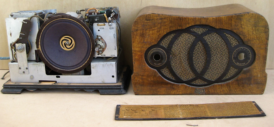 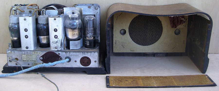 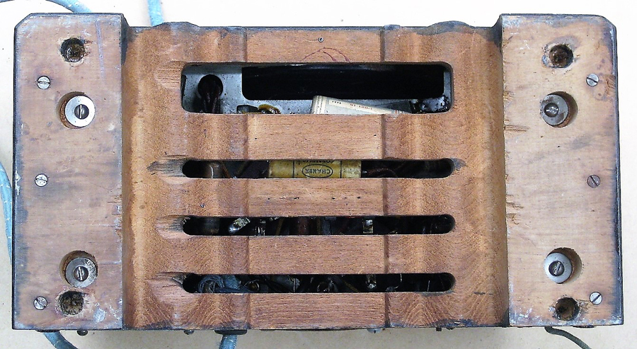 |
|
|
Return to top of page · Post #: 35 · Written at 9:36:19 PM on 18 September 2018.
|
|
|
|
Administrator
Location: Naremburn, NSW
Member since 15 November 2005 Member #: 1 Postcount: 7624 |
|
Photos uploaded to Post 34. ‾‾‾‾‾‾‾‾‾‾‾‾‾‾‾‾‾‾‾‾‾‾‾‾‾‾‾‾‾‾‾‾‾‾‾‾‾‾‾‾‾‾‾‾‾‾‾‾‾‾‾‾‾‾‾‾‾‾‾‾‾‾‾‾‾‾‾‾ A valve a day keeps the transistor away... |
|
|
Return to top of page · Post #: 36 · Written at 8:03:17 AM on 19 September 2018.
|
|
|
|
Location: NSW
Member since 10 June 2010 Member #: 681 Postcount: 1407 |
|
Thanks Brad. |
|
|
Return to top of page · Post #: 37 · Written at 1:30:31 PM on 23 September 2018.
|
|
|
|
Location: Perth, WA
Member since 19 November 2008 Member #: 381 Postcount: 240 |
|
Excellent photos does it have the change over switch? |
|
|
Return to top of page · Post #: 38 · Written at 4:17:22 PM on 23 September 2018.
|
|
|
|
Location: NSW
Member since 10 June 2010 Member #: 681 Postcount: 1407 |
|
Yes, it does have, but the wiring for it and the extension speaker change-over switch has been removed. The switch is visible in the top left hand corner of the first photo in post #26. |
|
|
Return to top of page · Post #: 39 · Written at 3:56:29 PM on 24 September 2018.
|
|
|
|
Location: Perth, WA
Member since 19 November 2008 Member #: 381 Postcount: 240 |
|
If the mice have eaten your back board label here is a replica you can cut out and use. |
|
|
Return to top of page · Post #: 40 · Written at 4:23:11 PM on 24 September 2018.
|
|
|
|
Location: NSW
Member since 10 June 2010 Member #: 681 Postcount: 1407 |
|
Thanks, but the backboard is OK. |
|
|
Return to top of page · Post #: 41 · Written at 9:22:21 PM on 24 September 2018.
|
|
|
|
Administrator
Location: Naremburn, NSW
Member since 15 November 2005 Member #: 1 Postcount: 7624 |
|
Document uploaded to Post 39. ‾‾‾‾‾‾‾‾‾‾‾‾‾‾‾‾‾‾‾‾‾‾‾‾‾‾‾‾‾‾‾‾‾‾‾‾‾‾‾‾‾‾‾‾‾‾‾‾‾‾‾‾‾‾‾‾‾‾‾‾‾‾‾‾‾‾‾‾ A valve a day keeps the transistor away... |
|
|
Return to top of page · Post #: 42 · Written at 10:38:21 AM on 25 September 2018.
|
|
|
|
Location: Perth, WA
Member since 19 November 2008 Member #: 381 Postcount: 240 |
|
The ARTS&P should be white plastic for 1934, blue sticker for 1935. |
|
|
Return to top of page · Post #: 43 · Written at 5:15:11 PM on 23 June 2025.
|
|
|
|
Location: Melbourne, VIC
Member since 22 June 2025 Member #: 2732 Postcount: 1 |
|
I am restoring a very early Astor Mickey OZ serial number 211. The schematic is not as per examples on internet or the HRSA supplement. |
|
|
Return to top of page · Post #: 44 · Written at 4:39:15 PM on 18 January 2026.
|
|
|
|
Location: Castle Hill, NSW
Member since 17 January 2025 Member #: 2698 Postcount: 46 |
|
I have found these post very useful as I begin work on my Astor Oz, which I picked up last year at the HRSA Auction in Melbourne. |
|
|
Return to top of page · Post #: 45 · Written at 9:14:57 AM on 19 January 2026.
|
|
|
|
Location: NSW
Member since 10 June 2010 Member #: 681 Postcount: 1407 |
|
I'll see what I have got later today. |
|
|
You need to be a member to post comments on this forum.
|
|
Sign In
Vintage Radio and Television is proudly brought to you by an era where things were built with pride and made to last.
DISCLAIMER: Valve radios and televisions contain voltages that can deliver lethal shocks. You should not attempt to work on a valve radio or other electrical appliances unless you know exactly what you are doing and have gained some experience with electronics and working around high voltages. The owner, administrators and staff of Vintage Radio & Television will accept no liability for any damage, injury or loss of life that comes as a result of your use or mis-use of information on this website. Please read our Safety Warning before using this website.
WARNING: Under no circumstances should you ever apply power to a vintage radio, television or other electrical appliance you have acquired without first having it checked and serviced by an experienced person. Also, at no time should any appliance be connected to an electricity supply if the power cord is damaged. If in doubt, do not apply power.
Shintara - Keepin' It Real · VileSilencer - Maintain The Rage