
General Discussion
Forum home - Go back to General discussion
|
Advice please
|
|
|
Return to top of page · Post #: 1 · Written at 1:04:48 PM on 24 February 2022.
|
|
|
|
Location: Silverstream Upperhutt, NZ
Member since 24 February 2022 Member #: 2485 Postcount: 19 |
|
Hi all Brian here I posted a bit of an intro in the other section |
|
|
Return to top of page · Post #: 2 · Written at 3:30:20 PM on 24 February 2022.
|
|

|
Administrator
Location: Naremburn, NSW
Member since 15 November 2005 Member #: 1 Postcount: 7587 |
|
G'day Brian, ‾‾‾‾‾‾‾‾‾‾‾‾‾‾‾‾‾‾‾‾‾‾‾‾‾‾‾‾‾‾‾‾‾‾‾‾‾‾‾‾‾‾‾‾‾‾‾‾‾‾‾‾‾‾‾‾‾‾‾‾‾‾‾‾‾‾‾‾ A valve a day keeps the transistor away... |
|
|
Return to top of page · Post #: 3 · Written at 4:15:13 PM on 24 February 2022.
|
|

|
Location: Sydney, NSW
Member since 28 January 2011 Member #: 823 Postcount: 6908 |
|
As well as describing the fault symptom(s), it will help greatly if you can specify the make and model of the radio. |
|
|
Return to top of page · Post #: 4 · Written at 7:03:10 PM on 24 February 2022.
|
|
|
|
Location: Silverstream Upperhutt, NZ
Member since 24 February 2022 Member #: 2485 Postcount: 19 |
|
Hi Guys and thanks for your welcome 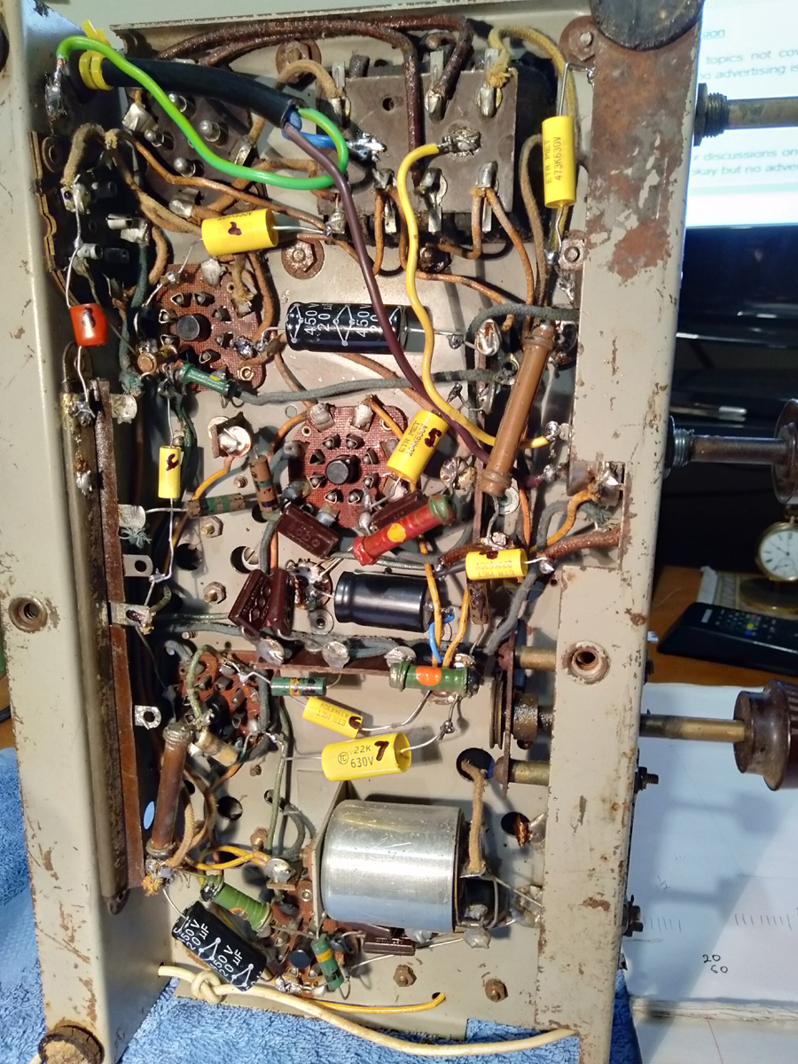 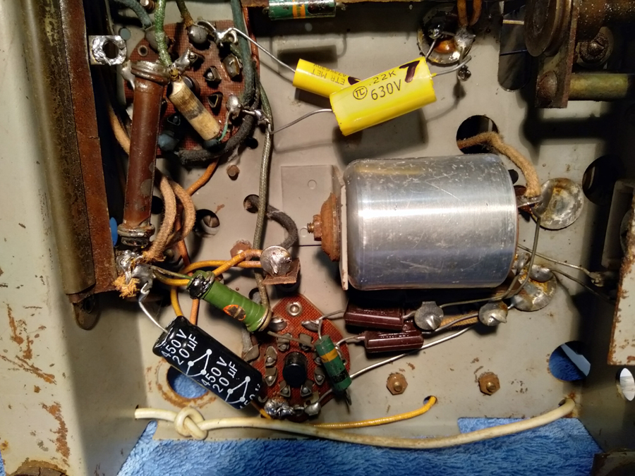 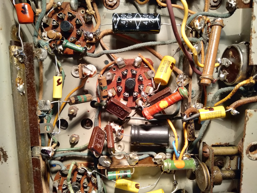 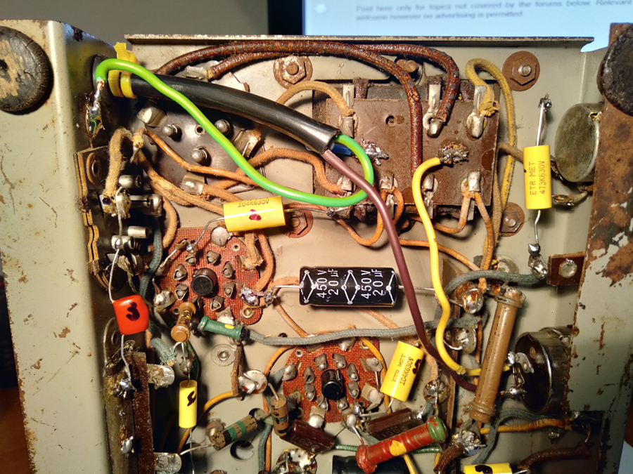 |
|
|
Return to top of page · Post #: 5 · Written at 7:43:25 PM on 24 February 2022.
|
|

|
Location: Hobart, TAS
Member since 31 July 2016 Member #: 1959 Postcount: 591 |
|
I know that this is no help in the current restoration. |
|
|
Return to top of page · Post #: 6 · Written at 7:46:12 PM on 24 February 2022.
|
|
|
|
Location: Linton, VIC
Member since 30 December 2016 Member #: 2028 Postcount: 472 |
|
Hi Powell, |
|
|
Return to top of page · Post #: 7 · Written at 7:49:10 PM on 24 February 2022.
|
|

|
Location: Hill Top, NSW
Member since 18 September 2015 Member #: 1801 Postcount: 2232 |
|
This seems to be the radio in question: |
|
|
Return to top of page · Post #: 8 · Written at 7:55:20 PM on 24 February 2022.
|
|
|
|
Location: Silverstream Upperhutt, NZ
Member since 24 February 2022 Member #: 2485 Postcount: 19 |
|
Thanks for that I have a picture of the schematic how do I post it |
|
|
Return to top of page · Post #: 9 · Written at 7:58:02 PM on 24 February 2022.
|
|
|
|
Location: Hill Top, NSW
Member since 18 September 2015 Member #: 1801 Postcount: 2232 |
|
You email pictures to Brad, look in his profile for the address. |
|
|
Return to top of page · Post #: 10 · Written at 8:01:18 PM on 24 February 2022.
|
|
|
|
Location: Silverstream Upperhutt, NZ
Member since 24 February 2022 Member #: 2485 Postcount: 19 |
|
Thanks found it and done |
|
|
Return to top of page · Post #: 11 · Written at 8:14:31 PM on 24 February 2022.
|
|
|
|
Location: Silverstream Upperhutt, NZ
Member since 24 February 2022 Member #: 2485 Postcount: 19 |
|
Thanks guys for all your replies. As I said and I will be straight up I dont yet understand what you guys are talking about yet so I will go with the transformer coil and try and figure that out. |
|
|
Return to top of page · Post #: 12 · Written at 8:19:39 PM on 24 February 2022.
|
|
|
|
Location: Hobart, TAS
Member since 31 July 2016 Member #: 1959 Postcount: 591 |
|
Just found the schematic, |
|
|
Return to top of page · Post #: 13 · Written at 8:37:41 PM on 24 February 2022.
|
|
|
|
Location: Hobart, TAS
Member since 31 July 2016 Member #: 1959 Postcount: 591 |
|
Just rereading your last post Powell. |
|
|
Return to top of page · Post #: 14 · Written at 8:40:30 PM on 24 February 2022.
|
|
|
|
Location: Silverstream Upperhutt, NZ
Member since 24 February 2022 Member #: 2485 Postcount: 19 |
|
I think I have found it bear with me here, its red in colour with a yellow dot in the middle and green at one end. ? |
|
|
Return to top of page · Post #: 15 · Written at 8:53:47 PM on 24 February 2022.
|
|
|
|
Location: Silverstream Upperhutt, NZ
Member since 24 February 2022 Member #: 2485 Postcount: 19 |
|
Hi JJ |
|
|
You need to be a member to post comments on this forum.
|
|
Sign In
Vintage Radio and Television is proudly brought to you by an era where things were built with pride and made to last.
DISCLAIMER: Valve radios and televisions contain voltages that can deliver lethal shocks. You should not attempt to work on a valve radio or other electrical appliances unless you know exactly what you are doing and have gained some experience with electronics and working around high voltages. The owner, administrators and staff of Vintage Radio & Television will accept no liability for any damage, injury or loss of life that comes as a result of your use or mis-use of information on this website. Please read our Safety Warning before using this website.
WARNING: Under no circumstances should you ever apply power to a vintage radio, television or other electrical appliance you have acquired without first having it checked and serviced by an experienced person. Also, at no time should any appliance be connected to an electricity supply if the power cord is damaged. If in doubt, do not apply power.
Shintara - Keepin' It Real · VileSilencer - Maintain The Rage