
General Discussion
Forum home - Go back to General discussion
|
Advice please
|
|
|
Return to top of page · Post #: 16 · Written at 9:02:30 PM on 24 February 2022.
|
|
|
|
Location: Silverstream Upperhutt, NZ
Member since 24 February 2022 Member #: 2485 Postcount: 19 |
|
Ive sent pictures to Brad to post for me 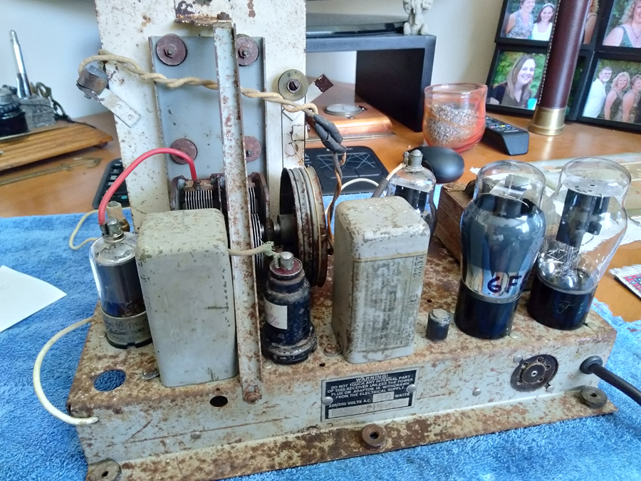 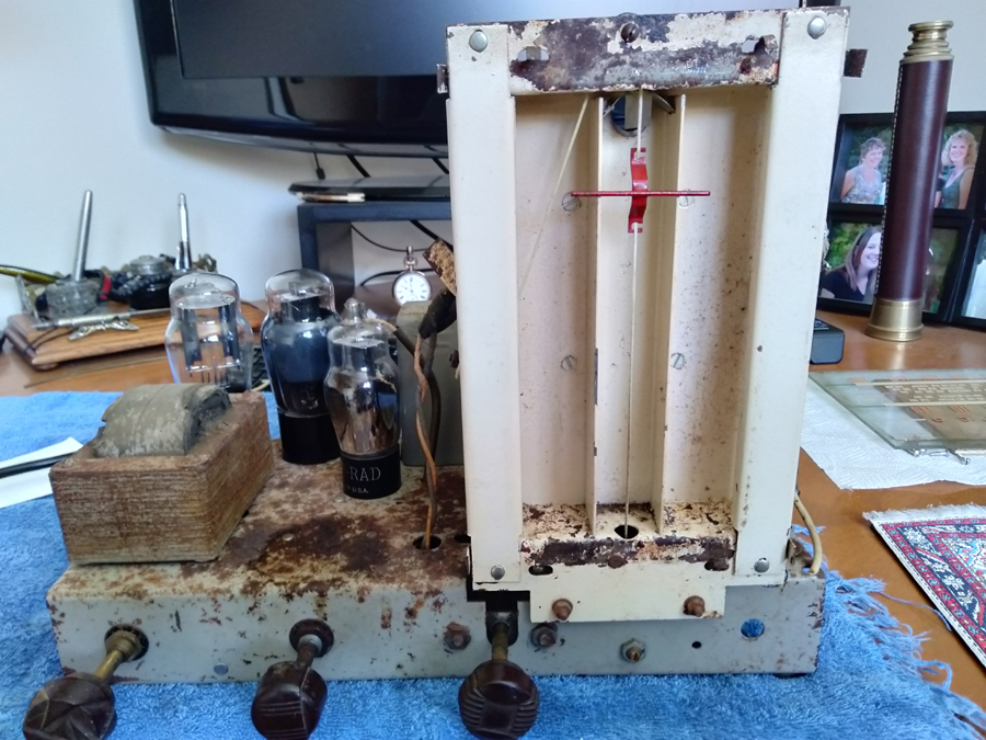 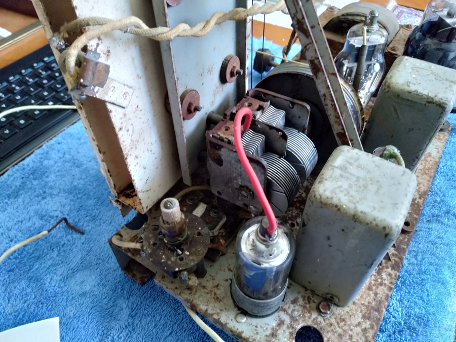 |
|
|
Return to top of page · Post #: 17 · Written at 10:21:35 PM on 24 February 2022.
|
|

|
Location: Wangaratta, VIC
Member since 21 February 2009 Member #: 438 Postcount: 5268 |
|
I have only had to deal with it about twice since the early sixties but that rather sounds like "Squegging" which will happen in the injection from the oscillator circuit. Most likely caused by replacing something one should not have replaced, or mis wired it. |
|
|
Return to top of page · Post #: 18 · Written at 10:45:57 PM on 24 February 2022.
|
|

|
Administrator
Location: Naremburn, NSW
Member since 15 November 2005 Member #: 1 Postcount: 7311 |
|
Photos uploaded to Post 4. ‾‾‾‾‾‾‾‾‾‾‾‾‾‾‾‾‾‾‾‾‾‾‾‾‾‾‾‾‾‾‾‾‾‾‾‾‾‾‾‾‾‾‾‾‾‾‾‾‾‾‾‾‾‾‾‾‾‾‾‾‾‾‾‾‾‾‾‾ A valve a day keeps the transistor away... |
|
|
Return to top of page · Post #: 19 · Written at 11:15:56 PM on 24 February 2022.
|
|

|
Location: Hill Top, NSW
Member since 18 September 2015 Member #: 1801 Postcount: 2018 |
|
Thanks Brad, that's better. Those resistors look like originals from 1940 when the radio was made, and at that advanced age I wouldn't trust any of them. Hopefully you've measured them all, to make sure they are still intact. |
|
|
Return to top of page · Post #: 20 · Written at 10:32:48 AM on 25 February 2022.
|
|
|
|
Location: Wangaratta, VIC
Member since 21 February 2009 Member #: 438 Postcount: 5268 |
|
There is one thing that needs doing: Check voltages. The -16V tells us if the set is working properly. That is back bias & all of the cathode current goes through it. If is wrong the set is notworking properly. |
|
|
Return to top of page · Post #: 21 · Written at 8:22:47 PM on 25 February 2022.
|
|
|
|
Location: Silverstream Upperhutt, NZ
Member since 24 February 2022 Member #: 2485 Postcount: 19 |
|
Thanks guys. Re replacing things that shouldn't be. I have not replaced any mica caps only the paper was and electrolytic. A couple of the paper ones were in real bad shape broken and was everywhere. Before removing a cap I drew what it was connected to recorded the value so I new were to replace it and only ever do one at a time |
|
|
Return to top of page · Post #: 22 · Written at 9:32:53 PM on 25 February 2022.
|
|

|
Location: Melbourne, VIC
Member since 20 September 2011 Member #: 1009 Postcount: 1182 |
|
Here is a link for the Courier EC (Radio (1936) Ltd) schematic. |
|
|
Return to top of page · Post #: 23 · Written at 10:24:45 PM on 25 February 2022.
|
|
|
|
Location: Wangaratta, VIC
Member since 21 February 2009 Member #: 438 Postcount: 5268 |
|
Some resistors like plate & grid can be measured in circuit. The generalisation being if its higher than spec. it needs further attention. I would expect the ones with green bodies & orange or yellow bands or dots to be out of spec. |
|
|
Return to top of page · Post #: 24 · Written at 5:38:11 PM on 27 February 2022.
|
|
|
|
Location: Silverstream Upperhutt, NZ
Member since 24 February 2022 Member #: 2485 Postcount: 19 |
|
I haven't had a chance to look at the resistors but have asked Brad to post a couple of pictures off the top of the chassis |
|
|
Return to top of page · Post #: 25 · Written at 10:25:06 PM on 27 February 2022.
|
|
|
|
Location: Wangaratta, VIC
Member since 21 February 2009 Member #: 438 Postcount: 5268 |
|
The metal tube circuit then, may be the right one? |
|
|
Return to top of page · Post #: 26 · Written at 6:58:09 PM on 28 February 2022.
|
|
|
|
Location: Silverstream Upperhutt, NZ
Member since 24 February 2022 Member #: 2485 Postcount: 19 |
|
Thanks marc |
|
|
Return to top of page · Post #: 27 · Written at 9:46:23 PM on 28 February 2022.
|
|
|
|
Location: Wangaratta, VIC
Member since 21 February 2009 Member #: 438 Postcount: 5268 |
|
The code has changed over the years, However the value assigned to the colours is fairly constant. In the style of the resistor mentioned a green body represents five. The black represents zero (0) and orange dot (4) as a multiply becomes 10 to the power of four. 5 0 0000 five hundred Kilo Ohms. with a green body, black end and an orange dot it would be 50K. |
|
|
Return to top of page · Post #: 28 · Written at 1:49:45 AM on 1 March 2022.
|
|
|
|
Location: Hill Top, NSW
Member since 18 September 2015 Member #: 1801 Postcount: 2018 |
|
Multiplier is simply how many extra noughts you add on the value. |
|
|
Return to top of page · Post #: 29 · Written at 10:48:57 AM on 1 March 2022.
|
|
|
|
Location: Wangaratta, VIC
Member since 21 February 2009 Member #: 438 Postcount: 5268 |
|
We should consider this in powers of ten as that also applies to capacitors. |
|
|
Return to top of page · Post #: 30 · Written at 4:22:57 PM on 1 March 2022.
|
|

|
Location: Latham, ACT
Member since 21 February 2015 Member #: 1705 Postcount: 2158 |
|
In Future restorations if you have a 80 or 5y3 rectifier valve you need the main filter caps to be rated at 600 volts! They are available and they do surge to 650 volts. Quite often the 80/5y3 will surge past 500 volts on warm up and most of the 450 volt electros dont surge much past 450 volts. |
|
|
You need to be a member to post comments on this forum.
|
|
Sign In
Vintage Radio and Television is proudly brought to you by an era where things were built with pride and made to last.
DISCLAIMER: Valve radios and televisions contain voltages that can deliver lethal shocks. You should not attempt to work on a valve radio or other electrical appliances unless you know exactly what you are doing and have gained some experience with electronics and working around high voltages. The owner, administrators and staff of Vintage Radio & Television will accept no liability for any damage, injury or loss of life that comes as a result of your use or mis-use of information on this website. Please read our Safety Warning before using this website.
WARNING: Under no circumstances should you ever apply power to a vintage radio, television or other electrical appliance you have acquired without first having it checked and serviced by an experienced person. Also, at no time should any appliance be connected to an electricity supply if the power cord is damaged. If in doubt, do not apply power.
Shintara - Keepin' It Real · VileSilencer - Maintain The Rage