
General Discussion
Forum home - Go back to General discussion
|
Help! Aristocrst or Salonola Radio.
|
|
|
Return to top of page · Post #: 1 · Written at 6:23:59 PM on 14 April 2010.
|
|

|
Location: Adelaide, SA
Member since 27 February 2010 Member #: 630 Postcount: 398 |
|
I have come across a unique radio. I am having trouble trying to work out what it is. It has a salonola badge on the front but looks exactly like the aristocrat 1051 ‾‾‾‾‾‾‾‾‾‾‾‾‾‾‾‾‾‾‾‾‾‾‾‾‾‾‾‾‾‾‾‾‾‾‾‾‾‾‾‾‾‾‾‾‾‾‾‾‾‾‾‾‾‾‾‾‾‾‾‾‾‾‾‾‾‾‾‾ Valve radios, They just don't make them like they used to |
|
|
Return to top of page · Post #: 2 · Written at 7:33:52 PM on 14 April 2010.
|
|

|
Administrator
Location: Naremburn, NSW
Member since 15 November 2005 Member #: 1 Postcount: 7643 |
|
I have little knowledge of Salonola though there is a reference that this brand was sold through Heiron and Smith, a company that now sells billiard tables. ‾‾‾‾‾‾‾‾‾‾‾‾‾‾‾‾‾‾‾‾‾‾‾‾‾‾‾‾‾‾‾‾‾‾‾‾‾‾‾‾‾‾‾‾‾‾‾‾‾‾‾‾‾‾‾‾‾‾‾‾‾‾‾‾‾‾‾‾ A valve a day keeps the transistor away... |
|
|
Return to top of page · Post #: 3 · Written at 7:55:30 PM on 14 April 2010.
|
|
|
|
Location: Adelaide, SA
Member since 27 February 2010 Member #: 630 Postcount: 398 |
|
Hmm ok. Well that makes things harder. anyone with ideas as to what the set might be? ‾‾‾‾‾‾‾‾‾‾‾‾‾‾‾‾‾‾‾‾‾‾‾‾‾‾‾‾‾‾‾‾‾‾‾‾‾‾‾‾‾‾‾‾‾‾‾‾‾‾‾‾‾‾‾‾‾‾‾‾‾‾‾‾‾‾‾‾ Valve radios, They just don't make them like they used to |
|
|
Return to top of page · Post #: 4 · Written at 12:32:33 AM on 15 April 2010.
|
|

|
Location: Wangaratta, VIC
Member since 21 February 2009 Member #: 438 Postcount: 5731 |
|
If the output transformer is not open? I have repaired several, where the wire insulation only, has failed. Take a carefull look before daring to toss it. |
|
|
Return to top of page · Post #: 5 · Written at 7:38:00 PM on 15 April 2010.
|
|
|
|
Location: Adelaide, SA
Member since 27 February 2010 Member #: 630 Postcount: 398 |
|
Ok... ‾‾‾‾‾‾‾‾‾‾‾‾‾‾‾‾‾‾‾‾‾‾‾‾‾‾‾‾‾‾‾‾‾‾‾‾‾‾‾‾‾‾‾‾‾‾‾‾‾‾‾‾‾‾‾‾‾‾‾‾‾‾‾‾‾‾‾‾ Valve radios, They just don't make them like they used to |
|
|
Return to top of page · Post #: 6 · Written at 10:09:32 PM on 15 April 2010.
|
|
|
|
Location: Wangaratta, VIC
Member since 21 February 2009 Member #: 438 Postcount: 5731 |
|
At the time of writing both valve data books have escaped to the workshop. However, I think that the filament current is different 5Z4 is more. |
|
|
Return to top of page · Post #: 7 · Written at 10:32:47 PM on 15 April 2010.
|
|
|
|
Location: Adelaide, SA
Member since 27 February 2010 Member #: 630 Postcount: 398 |
|
Thanks for the info. I will try and FIX? the o/p transformer. The rubber coating is cracked off where it enters the black (Some hard plastic or rubber) base of the transformer. I just hope that soldering to the wire will allow me to attach a set of fly leads to replace the cracked and perrished leads. The field windings are covered using the cotton braid, and look in good condition. ‾‾‾‾‾‾‾‾‾‾‾‾‾‾‾‾‾‾‾‾‾‾‾‾‾‾‾‾‾‾‾‾‾‾‾‾‾‾‾‾‾‾‾‾‾‾‾‾‾‾‾‾‾‾‾‾‾‾‾‾‾‾‾‾‾‾‾‾ Valve radios, They just don't make them like they used to |
|
|
Return to top of page · Post #: 8 · Written at 11:12:20 PM on 15 April 2010.
|
|
|
|
Location: Wangaratta, VIC
Member since 21 February 2009 Member #: 438 Postcount: 5731 |
|
If that is an ISO transformer the transformer is set in pitch alternatively, some were covered in pitch. 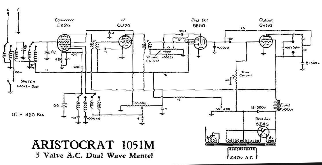 Click on image for larger resolution |
|
|
Return to top of page · Post #: 9 · Written at 11:18:19 PM on 15 April 2010.
|
|
|
|
Location: Adelaide, SA
Member since 27 February 2010 Member #: 630 Postcount: 398 |
|
Thanks ‾‾‾‾‾‾‾‾‾‾‾‾‾‾‾‾‾‾‾‾‾‾‾‾‾‾‾‾‾‾‾‾‾‾‾‾‾‾‾‾‾‾‾‾‾‾‾‾‾‾‾‾‾‾‾‾‾‾‾‾‾‾‾‾‾‾‾‾ Valve radios, They just don't make them like they used to |
|
|
Return to top of page · Post #: 10 · Written at 6:55:55 PM on 17 April 2010.
|
|
|
|
Location: Adelaide, SA
Member since 27 February 2010 Member #: 630 Postcount: 398 |
|
Hi Marc ‾‾‾‾‾‾‾‾‾‾‾‾‾‾‾‾‾‾‾‾‾‾‾‾‾‾‾‾‾‾‾‾‾‾‾‾‾‾‾‾‾‾‾‾‾‾‾‾‾‾‾‾‾‾‾‾‾‾‾‾‾‾‾‾‾‾‾‾ Valve radios, They just don't make them like they used to |
|
|
Return to top of page · Post #: 11 · Written at 7:54:56 PM on 17 April 2010.
|
|
|
|
Administrator
Location: Naremburn, NSW
Member since 15 November 2005 Member #: 1 Postcount: 7643 |
|
Sorry chaps, I've been working on the development of the new website and this has taken me away from day to day duties at times. Circuit diagram is now uploaded. ‾‾‾‾‾‾‾‾‾‾‾‾‾‾‾‾‾‾‾‾‾‾‾‾‾‾‾‾‾‾‾‾‾‾‾‾‾‾‾‾‾‾‾‾‾‾‾‾‾‾‾‾‾‾‾‾‾‾‾‾‾‾‾‾‾‾‾‾ A valve a day keeps the transistor away... |
|
|
Return to top of page · Post #: 12 · Written at 8:19:48 PM on 17 April 2010.
|
|
|
|
Location: Adelaide, SA
Member since 27 February 2010 Member #: 630 Postcount: 398 |
|
Thanks ‾‾‾‾‾‾‾‾‾‾‾‾‾‾‾‾‾‾‾‾‾‾‾‾‾‾‾‾‾‾‾‾‾‾‾‾‾‾‾‾‾‾‾‾‾‾‾‾‾‾‾‾‾‾‾‾‾‾‾‾‾‾‾‾‾‾‾‾ Valve radios, They just don't make them like they used to |
|
|
Return to top of page · Post #: 13 · Written at 8:43:37 PM on 17 April 2010.
|
|
|
|
Administrator
Location: Naremburn, NSW
Member since 15 November 2005 Member #: 1 Postcount: 7643 |
|
1. I can't guess why that is the case. ‾‾‾‾‾‾‾‾‾‾‾‾‾‾‾‾‾‾‾‾‾‾‾‾‾‾‾‾‾‾‾‾‾‾‾‾‾‾‾‾‾‾‾‾‾‾‾‾‾‾‾‾‾‾‾‾‾‾‾‾‾‾‾‾‾‾‾‾ A valve a day keeps the transistor away... |
|
|
Return to top of page · Post #: 14 · Written at 8:48:51 PM on 17 April 2010.
|
|
|
|
Location: Adelaide, SA
Member since 27 February 2010 Member #: 630 Postcount: 398 |
|
Uploading pictures Sounds like a great idea. The only thing I can think of is the size limits of your storage. I take it you host this site yourself, but the amount of pictures that may come could soon blow out your storage. ‾‾‾‾‾‾‾‾‾‾‾‾‾‾‾‾‾‾‾‾‾‾‾‾‾‾‾‾‾‾‾‾‾‾‾‾‾‾‾‾‾‾‾‾‾‾‾‾‾‾‾‾‾‾‾‾‾‾‾‾‾‾‾‾‾‾‾‾ Valve radios, They just don't make them like they used to |
|
|
Return to top of page · Post #: 15 · Written at 9:21:03 PM on 17 April 2010.
|
|
|
|
Location: Wangaratta, VIC
Member since 21 February 2009 Member #: 438 Postcount: 5731 |
|
Circuit sent direct |
|
|
You need to be a member to post comments on this forum.
|
|


Sign In
Vintage Radio and Television is proudly brought to you by an era where things were built with pride and made to last.
DISCLAIMER: Valve radios and televisions contain voltages that can deliver lethal shocks. You should not attempt to work on a valve radio or other electrical appliances unless you know exactly what you are doing and have gained some experience with electronics and working around high voltages. The owner, administrators and staff of Vintage Radio & Television will accept no liability for any damage, injury or loss of life that comes as a result of your use or mis-use of information on this website. Please read our Safety Warning before using this website.
WARNING: Under no circumstances should you ever apply power to a vintage radio, television or other electrical appliance you have acquired without first having it checked and serviced by an experienced person. Also, at no time should any appliance be connected to an electricity supply if the power cord is damaged. If in doubt, do not apply power.
Shintara - Keepin' It Real · VileSilencer - Maintain The Rage