
General Discussion
Forum home - Go back to General discussion
|
Help! Aristocrst or Salonola Radio.
|
|
|
Return to top of page · Post #: 16 · Written at 9:38:03 PM on 17 April 2010.
|
|

|
Administrator
Location: Naremburn, NSW
Member since 15 November 2005 Member #: 1 Postcount: 7307 |
|
Uploading pictures Sounds like a great idea. The only thing I can think of is the size limits of your storage. I take it you host this site yourself, but the amount of pictures that may come could soon blow out your storage. ‾‾‾‾‾‾‾‾‾‾‾‾‾‾‾‾‾‾‾‾‾‾‾‾‾‾‾‾‾‾‾‾‾‾‾‾‾‾‾‾‾‾‾‾‾‾‾‾‾‾‾‾‾‾‾‾‾‾‾‾‾‾‾‾‾‾‾‾ A valve a day keeps the transistor away... |
|
|
Return to top of page · Post #: 17 · Written at 9:57:08 PM on 17 April 2010.
|
|

|
Location: Wangaratta, VIC
Member since 21 February 2009 Member #: 438 Postcount: 5258 |
|
That 1051 circuit was always going to be WYSWYG. The original was ordinary, the one first referenced, was ordinary. |
|
|
Return to top of page · Post #: 18 · Written at 10:07:59 PM on 17 April 2010.
|
|

|
Location: Adelaide, SA
Member since 27 February 2010 Member #: 630 Postcount: 392 |
|
The caps in question are a white flat looking one. (Havent come across them before) I can see into the end of one and whatever it is made of is cracked and dryed out looking. The writing on then cant be read. And there is alot of solder spatter around this area and has been played with by someone. The volume and Tone control have been changed and the one that is in there at the moment dosnt have the second wiper output. ‾‾‾‾‾‾‾‾‾‾‾‾‾‾‾‾‾‾‾‾‾‾‾‾‾‾‾‾‾‾‾‾‾‾‾‾‾‾‾‾‾‾‾‾‾‾‾‾‾‾‾‾‾‾‾‾‾‾‾‾‾‾‾‾‾‾‾‾ Valve radios, They just don't make them like they used to |
|
|
Return to top of page · Post #: 19 · Written at 10:24:19 PM on 17 April 2010.
|
|
|
|
Administrator
Location: Naremburn, NSW
Member since 15 November 2005 Member #: 1 Postcount: 7307 |
|
I think the best source of pots is to buy rusty and crappy chassis as cheaply as possible and wreck them for spare parts. The other source is auction websites. Quite often boxes of spare parts are offered with pots, binding posts, power plugs and IF coils high on the list of avaliable goodies. None are new but often these parts can be put back into service. ‾‾‾‾‾‾‾‾‾‾‾‾‾‾‾‾‾‾‾‾‾‾‾‾‾‾‾‾‾‾‾‾‾‾‾‾‾‾‾‾‾‾‾‾‾‾‾‾‾‾‾‾‾‾‾‾‾‾‾‾‾‾‾‾‾‾‾‾ A valve a day keeps the transistor away... |
|
|
Return to top of page · Post #: 20 · Written at 10:44:19 PM on 17 April 2010.
|
|
|
|
Location: Adelaide, SA
Member since 27 February 2010 Member #: 630 Postcount: 392 |
|
Oh... Well it sounds like this might be put on hold for a while.... ‾‾‾‾‾‾‾‾‾‾‾‾‾‾‾‾‾‾‾‾‾‾‾‾‾‾‾‾‾‾‾‾‾‾‾‾‾‾‾‾‾‾‾‾‾‾‾‾‾‾‾‾‾‾‾‾‾‾‾‾‾‾‾‾‾‾‾‾ Valve radios, They just don't make them like they used to |
|
|
Return to top of page · Post #: 21 · Written at 7:01:53 PM on 18 April 2010.
|
|
|
|
Location: Adelaide, SA
Member since 27 February 2010 Member #: 630 Postcount: 392 |
|
Well.... ‾‾‾‾‾‾‾‾‾‾‾‾‾‾‾‾‾‾‾‾‾‾‾‾‾‾‾‾‾‾‾‾‾‾‾‾‾‾‾‾‾‾‾‾‾‾‾‾‾‾‾‾‾‾‾‾‾‾‾‾‾‾‾‾‾‾‾‾ Valve radios, They just don't make them like they used to |
|
|
Return to top of page · Post #: 22 · Written at 9:05:43 PM on 18 April 2010.
|
|
|
|
Location: Wangaratta, VIC
Member since 21 February 2009 Member #: 438 Postcount: 5258 |
|
Just consider the fact that I am actually a Chemist, albiet I have other qualifications, unrelated. |
|
|
Return to top of page · Post #: 23 · Written at 10:31:16 PM on 18 April 2010.
|
|
|
|
Location: Adelaide, SA
Member since 27 February 2010 Member #: 630 Postcount: 392 |
|
Ok good. I think I will do some more and get back to you. I will post up on monday or tuesday what I find. ‾‾‾‾‾‾‾‾‾‾‾‾‾‾‾‾‾‾‾‾‾‾‾‾‾‾‾‾‾‾‾‾‾‾‾‾‾‾‾‾‾‾‾‾‾‾‾‾‾‾‾‾‾‾‾‾‾‾‾‾‾‾‾‾‾‾‾‾ Valve radios, They just don't make them like they used to |
|
|
Return to top of page · Post #: 24 · Written at 10:33:17 PM on 19 April 2010.
|
|
|
|
Location: Wangaratta, VIC
Member since 21 February 2009 Member #: 438 Postcount: 5258 |
|
It may be an idea to post photo's. I normally advocate doing this before pulling things to bits, especially if there is no circuit diagram. If there is a senior moment, or the normal run of interuptions (eg today. started on a set & abandoned it twice for several hours) you at least can see where things were, before you fiddled. |
|
|
Return to top of page · Post #: 25 · Written at 7:13:57 PM on 21 April 2010.
|
|
|
|
Location: Adelaide, SA
Member since 27 February 2010 Member #: 630 Postcount: 392 |
|
Well after finding some time this is what I have found... 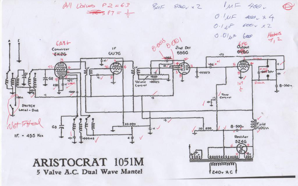 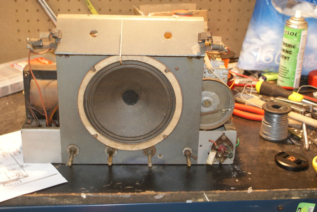 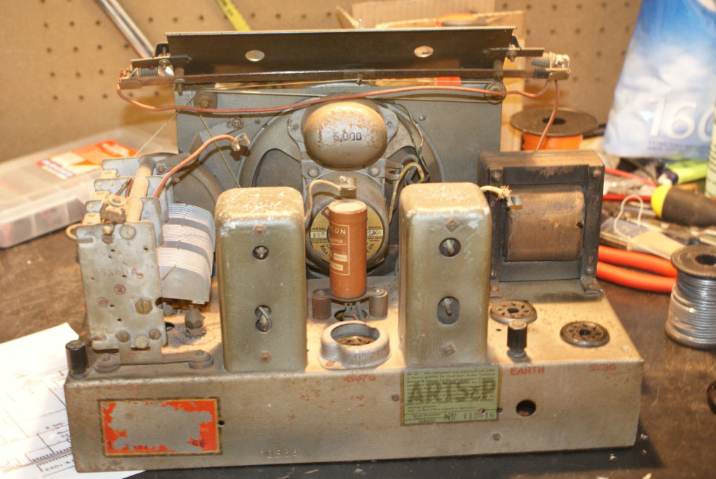 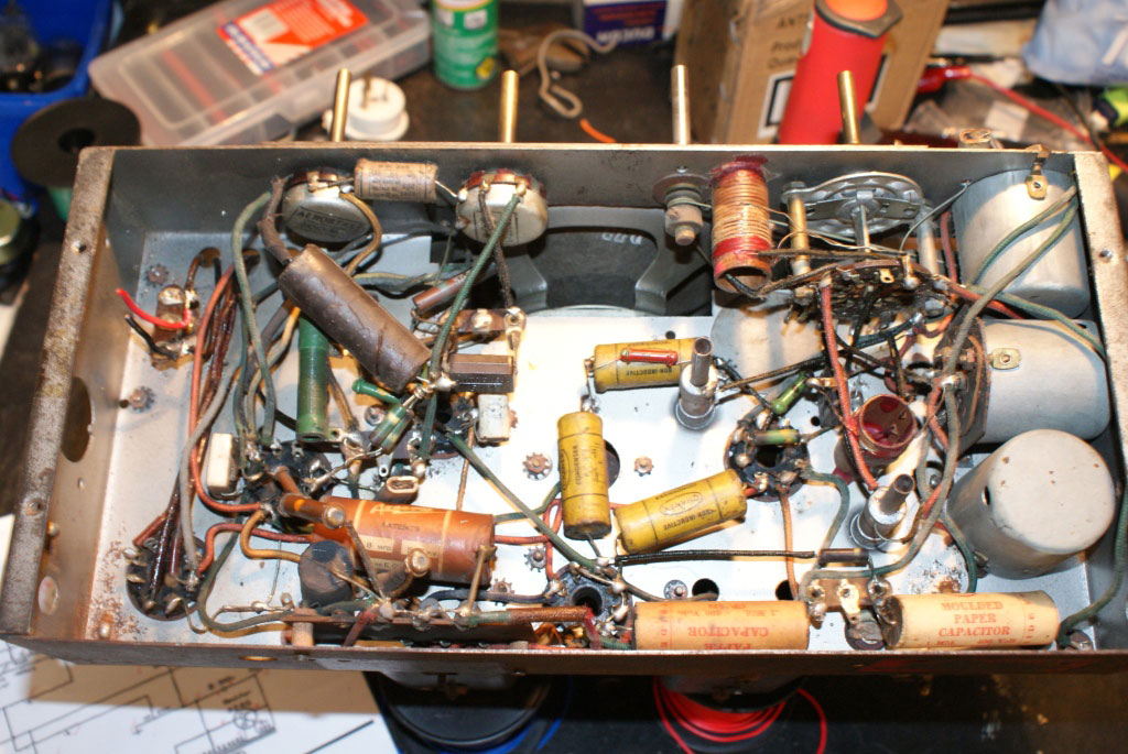 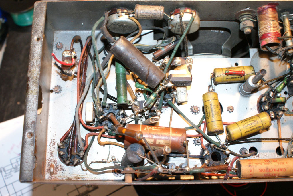 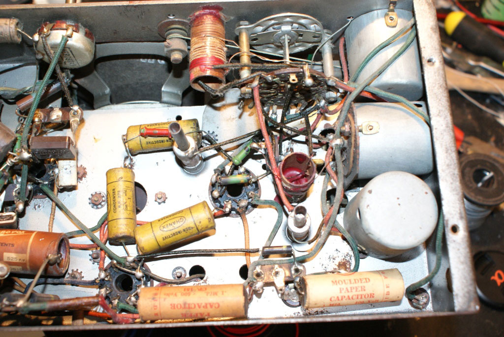 Click on image for larger resolution ‾‾‾‾‾‾‾‾‾‾‾‾‾‾‾‾‾‾‾‾‾‾‾‾‾‾‾‾‾‾‾‾‾‾‾‾‾‾‾‾‾‾‾‾‾‾‾‾‾‾‾‾‾‾‾‾‾‾‾‾‾‾‾‾‾‾‾‾ Valve radios, They just don't make them like they used to |
|
|
Return to top of page · Post #: 26 · Written at 10:52:40 PM on 21 April 2010.
|
|
|
|
Administrator
Location: Naremburn, NSW
Member since 15 November 2005 Member #: 1 Postcount: 7307 |
|
Photos are uploaded. ‾‾‾‾‾‾‾‾‾‾‾‾‾‾‾‾‾‾‾‾‾‾‾‾‾‾‾‾‾‾‾‾‾‾‾‾‾‾‾‾‾‾‾‾‾‾‾‾‾‾‾‾‾‾‾‾‾‾‾‾‾‾‾‾‾‾‾‾ A valve a day keeps the transistor away... |
|
|
Return to top of page · Post #: 27 · Written at 12:44:17 PM on 22 April 2010.
|
|
|
|
Location: Wangaratta, VIC
Member since 21 February 2009 Member #: 438 Postcount: 5258 |
|
There seem to be inconsistencies between what is and the assumed circuit. I am highly suspicious that the resistor feeding the screens would be one of those long wire wound types with tappings. |
|
|
Return to top of page · Post #: 28 · Written at 10:47:08 AM on 23 April 2010.
|
|
|
|
Location: Adelaide, SA
Member since 27 February 2010 Member #: 630 Postcount: 392 |
|
Hi there ‾‾‾‾‾‾‾‾‾‾‾‾‾‾‾‾‾‾‾‾‾‾‾‾‾‾‾‾‾‾‾‾‾‾‾‾‾‾‾‾‾‾‾‾‾‾‾‾‾‾‾‾‾‾‾‾‾‾‾‾‾‾‾‾‾‾‾‾ Valve radios, They just don't make them like they used to |
|
|
Return to top of page · Post #: 29 · Written at 9:58:44 PM on 23 April 2010.
|
|
|
|
Location: Wangaratta, VIC
Member since 21 February 2009 Member #: 438 Postcount: 5258 |
|
Circuit around the 6F6 will be similar to that of a 6V6 irrespective of brand, most of them followed a similar plot, with minor variations. |
|
|
Return to top of page · Post #: 30 · Written at 6:16:47 AM on 25 April 2010.
|
|
|
|
Location: Adelaide, SA
Member since 27 February 2010 Member #: 630 Postcount: 392 |
|
Ok thanks I will keep that in mind. I just cant wait for the parts to arrive so I can start to put this thing back together. ‾‾‾‾‾‾‾‾‾‾‾‾‾‾‾‾‾‾‾‾‾‾‾‾‾‾‾‾‾‾‾‾‾‾‾‾‾‾‾‾‾‾‾‾‾‾‾‾‾‾‾‾‾‾‾‾‾‾‾‾‾‾‾‾‾‾‾‾ Valve radios, They just don't make them like they used to |
|
|
You need to be a member to post comments on this forum.
|
|


Sign In
Vintage Radio and Television is proudly brought to you by an era where things were built with pride and made to last.
DISCLAIMER: Valve radios and televisions contain voltages that can deliver lethal shocks. You should not attempt to work on a valve radio or other electrical appliances unless you know exactly what you are doing and have gained some experience with electronics and working around high voltages. The owner, administrators and staff of Vintage Radio & Television will accept no liability for any damage, injury or loss of life that comes as a result of your use or mis-use of information on this website. Please read our Safety Warning before using this website.
WARNING: Under no circumstances should you ever apply power to a vintage radio, television or other electrical appliance you have acquired without first having it checked and serviced by an experienced person. Also, at no time should any appliance be connected to an electricity supply if the power cord is damaged. If in doubt, do not apply power.
Shintara - Keepin' It Real · VileSilencer - Maintain The Rage