Welcome to Australia's only Vintage Radio and Television discussion forums. You are not logged in. Please log in below, apply for an account or retrieve your password.
Australian Vintage Radio Forums
  Home  ·  About Us  ·  Discussion Forums  ·  Glossary  ·  Outside Links  ·  Policies  ·  Services Directory  ·  Safety Warnings  ·  Tutorials

General Discussion

Forum home - Go back to General discussion

 Noob needs help with ID and next steps...
« Back · 1 · 2 · Next »
 Return to top of page · Post #: 1 · Written at 2:17:55 PM on 29 September 2018.
Pharmacisticus's Gravatar
 Location: Albury, NSW
 Member since 2 September 2018
 Member #: 2291
 Postcount: 5

Hi All,

I'm really new to this so you'll have to talk s-l-o-w-l-y.
I'm trying to repair an old Chieftain radiogram, hopefully, it will look like the picture attached one day...

I'm trying to get a positive ID on the chassis but haven't had much luck.
I've included pictures of what I have found so far.
I've been able to identify the following valves, 6AV6, 6BA6, 6BE6 and 6X4.
The two I can't ID are stumping me, the first one is short and fat like the other 6 series and has a 6 on it but the other numbers have been removed, the second one is taller and slim 7 pins with no markings except "I C /_\ 7" on the bottom.

I've looked at the schematics list online and I've gotten close but haven't found a true match for it.
I'd like to get started on changing out some of the capacitors but without the schematic, I'm feeling a bit lost...

Any advice would be greatly appreciated.

Have a great weekend,

Thanks,

Josh

Chieftain Console Valve Radio


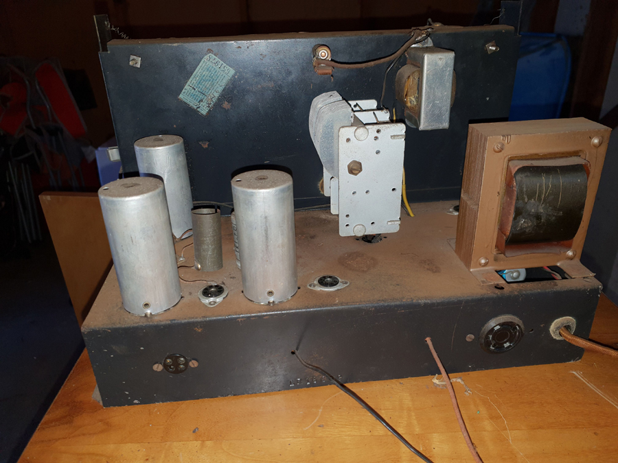
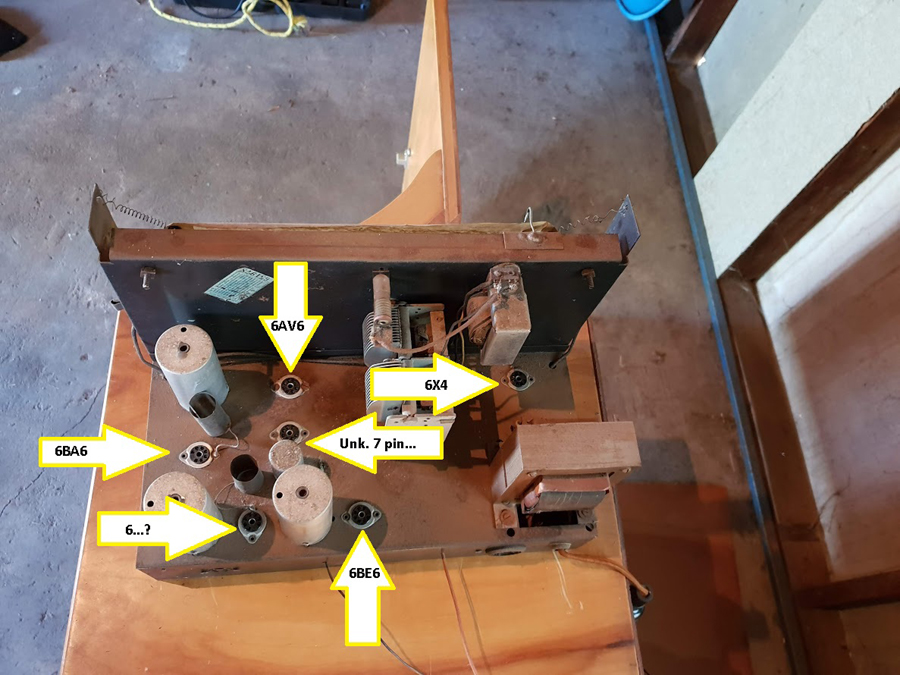
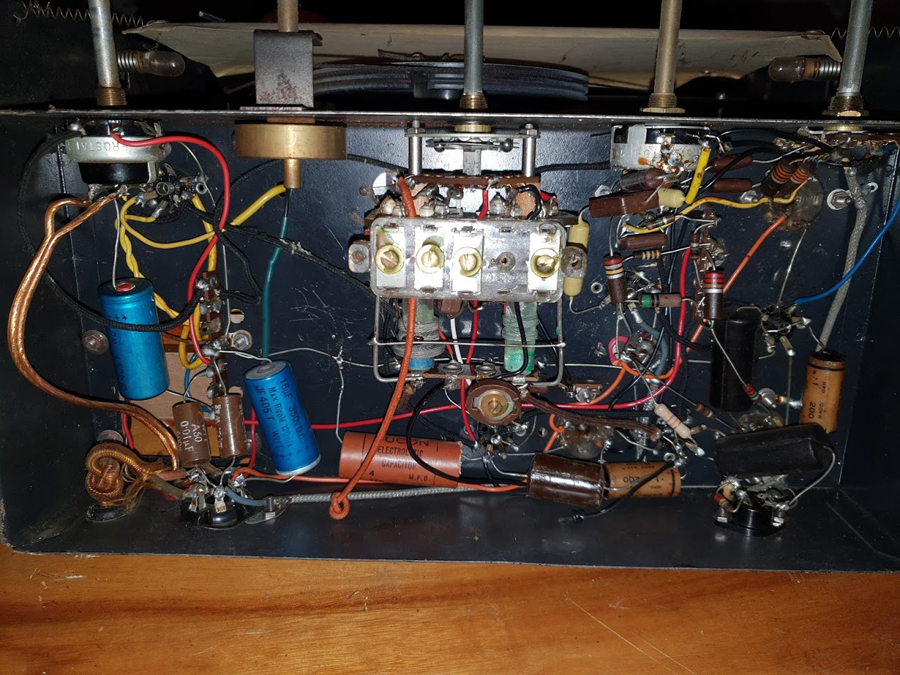
 Return to top of page · Post #: 2 · Written at 2:50:39 PM on 29 September 2018.
STC830's Gravatar
 Location: NSW
 Member since 10 June 2010
 Member #: 681
 Postcount: 1256

Hello Pharmacisticus

Welcome to the forum. One way of identifying valves that have had the numbers rubbed off them is to place the valve in the freezer for a while; when cooled right down take it out and look for any identification revealed by condensation.

This doesn't help with informed or uninformed substitutions in the life of the radio. There are many better informed forum members than me regarding substitutions and somebody should be able to help. Can you find anything that might be a model number for the radio?

A picture tells a thousand words, and if you submit one to the administrator Brad via his email, this will be a big help.

Have a good look at the safety warning at the bottom of the page especially if you don't have electrical or radio servicing experience.

Be careful you might get hooked on old radios once you get started! The almost infinite variety is fascinating.


 Return to top of page · Post #: 3 · Written at 3:26:32 PM on 29 September 2018.
JFB's Gravatar
 JFB
 Location: Milton, NSW
 Member since 27 June 2016
 Member #: 1945
 Postcount: 55

Hi Josh,

Not an exact match I know but my initial guess would be a model LF from 1955. The HSRA radio model spreadsheet lists the valve lineup as 6BA6, 6AN7, 6BA6, 6AV6, 6AQ5, 6X4 which aligns with what the Radio Museum site lists.

Doesn't explain the strange 6BE6 Pentagrid-Converter, the converter in the LF is the 6AN7. You can request a copy of the circuit diagram from the radio museum site https://www.radiomuseum.org/r/motorspare_chieftain_lf.html just click on the funny large extract of the circuit diagram and see if that helps.

Perhaps when the pictures are posted it may be clearer

Regards - Joe


 Return to top of page · Post #: 4 · Written at 3:42:50 PM on 29 September 2018.
Ian Robertson's Gravatar
 Location: Belrose, NSW
 Member since 31 December 2015
 Member #: 1844
 Postcount: 2371

Send Brad some clear, close-up pictures of the unknown valves (or email to me) and I should be able to tell you what they are.

BUT

If the tall one has 7 pins it will be a 6AQ5.

If the short one has 7 pins it will most likely be another 6BA6. If you peer into the connections in the base and compare, you should be able to confirm this. Better still, does the tuning gang have 3 sections? If so, yes, it will be a 6BA6.

But remember, valves in old radios rarely need to be replaced, or even tested, except in the radio itself. If you know where they belong, don't worry too much.

I suggest you bring the radio up with a dim bulb tester (60 watt incandescent light bulb in series with the power). See if it works at all, even if very badly. If so, replace wax paper caps one or two at a time and re-test, so if you make a mistake you will know where it is.

The lamp will protect the parts in the radio against most faults and it avoids smoke and drama on initial power-up after many years lying dormant.

My trick as a kid used to be connecting the aerial I had for my crystal set. This would "force-feed" a dead radio to get something out of it, then I'd work to improve it.


 Return to top of page · Post #: 5 · Written at 7:37:49 PM on 29 September 2018.
Robbbert's avatar
 Location: Hill Top, NSW
 Member since 18 September 2015
 Member #: 1801
 Postcount: 2014

I'd go with Ian's hypothesis - a 6AQ5 and most likely another 6BA6.

If you can read the values on the old waxed capacitors there's nothing stopping you from replacing them.
At least that will get you started while waiting for further identification.


 Return to top of page · Post #: 6 · Written at 7:57:06 PM on 29 September 2018.
Ian Robertson's Gravatar
 Location: Belrose, NSW
 Member since 31 December 2015
 Member #: 1844
 Postcount: 2371

If you are going to replace the caps all at once, take plenty of close-up pictures would be my advice. This comes from many years of trying to fault-find TVs that had been re-capped by apprentices. In most cases it would have been quicker if I'd done it myself!

But using my method, you won't need the circuit. And odds-on you won't need any new valves.


 Return to top of page · Post #: 7 · Written at 1:37:49 PM on 30 September 2018.
Pharmacisticus's Gravatar
 Location: Albury, NSW
 Member since 2 September 2018
 Member #: 2291
 Postcount: 5

Hi Everyone,

Thanks for so many intelligent and informative posts.

.STC830 - I've got the unknown valve in the freezer as we speak, waiting to see what appears... love the idea, elegant and simple

.JFB - Thanks for the tip, I was thinking the LF myself but when I downloaded the schematic and saw the different valves I started to
second guess myself!

.Ian Robertson - the tuning gang is the metals fins looking thing yeah? (sorry, remember I said to talk slowly!) in which case this only has 2.
That said I've had a look into the base and the second unidentified valve is wired the same way as my other 6BA6.

- Love the idea of the dim-bulb-tester, the original power cord had rendered down to bare metal, which I've replaced now,
but have been scared to fire it up again.

.Robbert - Thanks for that I'll get onto IDing the wax capacitors.

Cheers again everyone,
I did send some photos to Brad with the original post I'm sure they'll be put up soon.

Josh


 Return to top of page · Post #: 8 · Written at 2:22:50 PM on 30 September 2018.
Ian Robertson's Gravatar
 Location: Belrose, NSW
 Member since 31 December 2015
 Member #: 1844
 Postcount: 2371

Josh, the radio probably had a 2 core mains lead. I hope you fitted a 3 core lead, earthed the chassis securely with it and used a proper cable clamp for the power cord?

It's very important to earth vintage gear because the old insulation inside the transformer may break down and kill someone. You wouldn't want to be responsible for that happening I'm sure.

Do seriously consider taking my advice and only replace caps 1 or 2 at a time, checking in between. I normally start with the critical ones (6AQ5 output stage grid coupler, screen bypasses) and move on from there. Same as in a TV chassis but in this case the B+Boost cap is first to be replaced.


 Return to top of page · Post #: 9 · Written at 2:43:07 PM on 30 September 2018.
Pharmacisticus's Gravatar
 Location: Albury, NSW
 Member since 2 September 2018
 Member #: 2291
 Postcount: 5

Hi Ian,

Thanks for the reply.
The old unit definitely did have old 2 core mains lead, I wasn't sure about earthing this as there seemed to be some conjecture out there about if it was a good idea or not?
I was going to ask about this in another post later on when I was getting closer to powering up again.
Where do you suggest I attach the earth wire?

Hopefully, my photos go up soon, that said I took them before I remover the old lead.

I was trained as a projectionist years ago, and have a healthy respect for 240V and run all my gear through a portable RCD safety switch set.

I had heard that replacing the caps one at a time was the way to go.
When you say checking in between, do you mean a checking that it still powers up and makes noise or something more precise/technical?

Thanks again,

Josh


 Return to top of page · Post #: 10 · Written at 4:14:45 PM on 30 September 2018.
Marcc's avatar
 Location: Wangaratta, VIC
 Member since 21 February 2009
 Member #: 438
 Postcount: 5254

7 pin possibly audio out 6AQ5: 6AN7 (pentagrid) is taller & has nine pins 6BE6 has seven.

Two 6BA6 would suggest that perhaps one is an RF pre amp. That would cause the set to have a three gang tuner.

It would likely then be 1st RF 6BA6; Mixer/ osc. 6BE6; 1st IF 6BA6; 2nd detector 1st Audio 6AV6; Output 6AQ5. Rectifier 6X4.

Beware 6AQ5 has two control grid pins: One & seven so using an ohm meter with the tube out. that should be a short. Heater is pins 3&4 and they should also show continuity.

That combination of valves is very common.

If it's LF it should have the 9 pin 6AN7, I have circuit.

Marc


 Return to top of page · Post #: 11 · Written at 5:15:47 PM on 30 September 2018.
Ian Robertson's Gravatar
 Location: Belrose, NSW
 Member since 31 December 2015
 Member #: 1844
 Postcount: 2371

Hi Josh

Hot chassis radios, as found in the US and Europe, cannot be earthed and need special cabinet provisions. The vast majority of Oz gear has an isolation transformer and hence a grounded chassis.

Earth is commonly connected to a lug under a transformer mounting bolt. You can get plastic cable glands from Jaycar etc. as well as electrical wholesalers that will clamp the power cable safely. Rule of thumb - you should be able to safely hang the chassis up from the power cord.

Strange it has two 6BA6s but only a two section tuning gang. Maybe it has two IF stages? Possible. Untuned RF amps are rare. Pictures would help.

Maybe the unmarked 6BA6 is really a 6AU6 - they look identical - and it's a preamp for a magnetic pickup cartridge? Also possible.

Checking in between? Just check that you can still get sound out of it between cap changes, i.e. that you haven't broken something.


 Return to top of page · Post #: 12 · Written at 10:38:13 PM on 30 September 2018.
Marcc's avatar
 Location: Wangaratta, VIC
 Member since 21 February 2009
 Member #: 438
 Postcount: 5254

Perhaps we need a photo? If it is an LF it has to have three gangs that's on the circuit & V1 & V3 are 6BA6 both have AGC applied to them. Set is back biased as another clue.


 Return to top of page · Post #: 13 · Written at 3:57:11 PM on 1 October 2018.
Pharmacisticus's Gravatar
 Location: Albury, NSW
 Member since 2 September 2018
 Member #: 2291
 Postcount: 5

Hi All,

I can't handle the suspense any longer!

I've posted links to the photos of the chassis...

This is what I'm hoping the unit will look like when I'm finished
https://drive.google.com/open?id=1MT62XtRKxwyL4p_hH80sj96TcWIi8eBz

This is the chassis from the top down with the valve placement noted.
https://drive.google.com/open?id=1goZXouLRZu2iYVCUcLK7oqTUiGH7iu39

This is the chassis side on.
https://drive.google.com/open?id=1HFkUtRxfh4ZFYhdah0ZwxADA1jK7cKxa

This is the underside of the chassis.
https://drive.google.com/open?id=15RfmboAySy9pU2-r66uUG0aWu9NGZ_75

Hope that helps!

Cheers again - Josh


 Return to top of page · Post #: 14 · Written at 4:24:26 PM on 1 October 2018.
STC830's Gravatar
 Location: NSW
 Member since 10 June 2010
 Member #: 681
 Postcount: 1256

The back of chassis picture shows the stamping LR16809 which suggests model LR prefix. This prefix is not in the Radiohistory (http://hws.org.au/RadioHistory/manufacturers/cccx.htm) list. So maybe this is one model that didn't make that list. A not unusual occurrence in other publications of Australian radios such Australian Official Radio Service Manual (AORSM) and others.

However looks nice and clean underneath and hopefully untouched, so restoration should be easy if none of the transformers (power, speaker or interstage) have failed.


 Return to top of page · Post #: 15 · Written at 4:41:56 PM on 1 October 2018.
Pharmacisticus's Gravatar
 Location: Albury, NSW
 Member since 2 September 2018
 Member #: 2291
 Postcount: 5

Hi ST830,

Thanks for the interest.
I think the stamping is LR16899, but is hard to read in the previous pictures, it's a bit clearer in the pic I have of it still in the cabinet.
https://drive.google.com/open?id=1kILL3HhCkBOE5C5SDU7E_t2dqwVuFF7NcA

Not sure if that helps at all?

Glad you think it looks clean from underneath, there was a dead mouse in there when I opened it up!

Cheers,

Josh


« Back · 1 · 2 · Next »
 You need to be a member to post comments on this forum.

Sign In

Username:
Password:
 Keep me logged in.
Do not tick box on a computer with public access.