
General Discussion
Forum home - Go back to General discussion
|
Airzone or Prefect
|
|
|
Return to top of page · Post #: 16 · Written at 1:11:04 PM on 10 September 2017.
|
|

|
Location: Sydney, NSW
Member since 28 January 2011 Member #: 823 Postcount: 6692 |
|
What valves are in this radio? |
|
|
Return to top of page · Post #: 17 · Written at 2:00:32 PM on 10 September 2017.
|
|

|
Location: Latham, ACT
Member since 21 February 2015 Member #: 1705 Postcount: 2158 |
|
No it's not a secret some of the valves are in a very tight place and I don't want to create issues getting them out as they are working. I am being a bit of a woos lol. The out put valve is a 1q5gt and another is a 1a7gt , the other two are in a very hard to get position, one of them has a shield on it . They are all octal valves , not the miniature ones. |
|
|
Return to top of page · Post #: 18 · Written at 2:39:52 PM on 10 September 2017.
|
|
|
|
Location: Sydney, NSW
Member since 28 January 2011 Member #: 823 Postcount: 6692 |
|
1A7 and 1A5, along with 1H5 are commonly found in many battery sets of that era. The other one is likely 1N5 or 1P5. |
|
|
Return to top of page · Post #: 19 · Written at 10:44:56 AM on 11 September 2017.
|
|
|
|
Location: Latham, ACT
Member since 21 February 2015 Member #: 1705 Postcount: 2158 |
|
Well the next episode for this little set is that its going to be professionally recovered so I will have it up to new standards yaay. |
|
|
Return to top of page · Post #: 20 · Written at 11:56:27 AM on 11 September 2017.
|
|

|
Location: Wangaratta, VIC
Member since 21 February 2009 Member #: 438 Postcount: 5267 |
|
Well if it is going to be professionally recovered, then the chassis is going to have to be out of it, & there should (depending on the socket) be a way of pushing the spigot up & then levering the valve out, rather than risk damage pulling it out by the glass. |
|
|
Return to top of page · Post #: 21 · Written at 1:12:05 PM on 11 September 2017.
|
|
|
|
Location: Latham, ACT
Member since 21 February 2015 Member #: 1705 Postcount: 2158 |
|
Well it is out of the case and I might get a little braver and do that but its whats above the valve that concerns me. |
|
|
Return to top of page · Post #: 22 · Written at 9:57:36 PM on 13 September 2017.
|
|
|
|
Location: Latham, ACT
Member since 21 February 2015 Member #: 1705 Postcount: 2158 |
|
Took this baby to the fellow to see what he thought about it and its going to get the leather treatment. He showed me a piece of thin leather which is very very close to the thickness of the original leatherette . He does a awesome job and I have told him to take his time and I dont expect it to be done for nicks. The price he quoted was 160 bucks but it includes all new fittings and will look a million bucks. 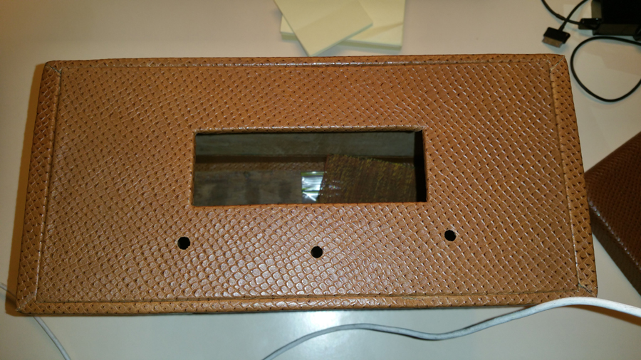  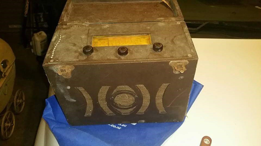  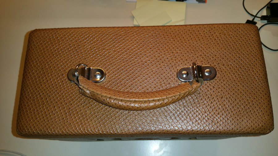 |
|
|
Return to top of page · Post #: 23 · Written at 8:55:17 PM on 14 September 2017.
|
|
|
|
Location: Latham, ACT
Member since 21 February 2015 Member #: 1705 Postcount: 2158 |
|
One question I have with this one. When I recapped it I replaced a 25μF 40 volt electro with a 24μF 600 volt electro only because I didnt want to drive unnessasarily to Jaycar when I had something on hand that would work. Is the higher voltage a issue here I am going to check the resistors this weekend and I may just swap the electro out for something smaller. |
|
|
Return to top of page · Post #: 24 · Written at 10:40:41 PM on 14 September 2017.
|
|
|
|
Location: Sydney, NSW
Member since 28 January 2011 Member #: 823 Postcount: 6692 |
|
Using a higher working voltage than necessary for a given capacitance may result in a higher ESR, which may or may not have implications for the circuit it's used in. |
|
|
Return to top of page · Post #: 25 · Written at 1:46:35 AM on 15 September 2017.
|
|

|
Location: Hill Top, NSW
Member since 18 September 2015 Member #: 1801 Postcount: 2018 |
|
I assume the 25μF was connected between the output valve's cathode and chassis. |
|
|
Return to top of page · Post #: 26 · Written at 2:02:54 PM on 19 September 2017.
|
|
|
|
Location: Belrose, NSW
Member since 31 December 2015 Member #: 1844 Postcount: 2375 |
|
Hey Rob, this is a battery set! No cathode bypasses.... |
|
|
Return to top of page · Post #: 27 · Written at 10:30:01 PM on 19 September 2017.
|
|

|
Administrator
Location: Naremburn, NSW
Member since 15 November 2005 Member #: 1 Postcount: 7311 |
|
Photos uploaded to Post 22. ‾‾‾‾‾‾‾‾‾‾‾‾‾‾‾‾‾‾‾‾‾‾‾‾‾‾‾‾‾‾‾‾‾‾‾‾‾‾‾‾‾‾‾‾‾‾‾‾‾‾‾‾‾‾‾‾‾‾‾‾‾‾‾‾‾‾‾‾ A valve a day keeps the transistor away... |
|
|
Return to top of page · Post #: 28 · Written at 4:41:12 PM on 23 September 2017.
|
|
|
|
Location: Latham, ACT
Member since 21 February 2015 Member #: 1705 Postcount: 2158 |
|
1Q5GT, 1A7GT, 1H5GT and 1P5GT is the valve lineup for this set. Finally got the nerve to pull them out only to find them pencilled in on the chassis anyway doooh. I have replaced the speaker tranny and checked all resistors. It's still distorted, what could be causing that maybe a weak valve or the speaker tranny being unshielded ( original was shielded and tropicalised ) and close to the tuning gang. |
|
|
Return to top of page · Post #: 29 · Written at 10:50:42 PM on 24 September 2017.
|
|
|
|
Location: Latham, ACT
Member since 21 February 2015 Member #: 1705 Postcount: 2158 |
|
Well we finally found the issue with this little set. When I replaced the speaker transformer, the new one upset the feedback circuit and had to fit a smaller capacitor. It now performs loud and clear. All I need to do is start putting it back together. |
|
|
Return to top of page · Post #: 30 · Written at 6:07:01 AM on 30 September 2017.
|
|
|
|
Location: Latham, ACT
Member since 21 February 2015 Member #: 1705 Postcount: 2158 |
|
This little set is working perfectly now. I am leaning towards it being made by HMV as I have a HMV portable with the exact same knobs. the case is getting a little bling as I am replacing the hinges and catches with Brass items. |
|
|
You need to be a member to post comments on this forum.
|
|

Sign In
Vintage Radio and Television is proudly brought to you by an era where things were built with pride and made to last.
DISCLAIMER: Valve radios and televisions contain voltages that can deliver lethal shocks. You should not attempt to work on a valve radio or other electrical appliances unless you know exactly what you are doing and have gained some experience with electronics and working around high voltages. The owner, administrators and staff of Vintage Radio & Television will accept no liability for any damage, injury or loss of life that comes as a result of your use or mis-use of information on this website. Please read our Safety Warning before using this website.
WARNING: Under no circumstances should you ever apply power to a vintage radio, television or other electrical appliance you have acquired without first having it checked and serviced by an experienced person. Also, at no time should any appliance be connected to an electricity supply if the power cord is damaged. If in doubt, do not apply power.
Shintara - Keepin' It Real · VileSilencer - Maintain The Rage