Welcome to Australia's only Vintage Radio and Television discussion forums. You are not logged in. Please log in below, apply for an account or retrieve your password.
Australian Vintage Radio Forums
  Home  ·  About Us  ·  Discussion Forums  ·  Glossary  ·  Outside Links  ·  Policies  ·  Services Directory  ·  Safety Warnings  ·  Tutorials

General Discussion

Forum home - Go back to General discussion

 Palec WYA 4456 multitester Mk1
« Back · 1 · Next »
 Return to top of page · Post #: 1 · Written at 3:11:34 PM on 3 February 2017.
Stan Dean's Gravatar
 Location: Dromana, VIC
 Member since 27 December 2016
 Member #: 2025
 Postcount: 16

Can anyone help me?
I have finally opened up my treasure. but I can't start to refurbish it as I have discovered that a valve is missing. The rectifier valve is still there (6X5) but I have no idea what the missing valve should be or what it does, except that is a 6 pin base. I am still looking for a diagram for the unit to make life easier, but the wiring, although it looks complicated at first glance, with time I feel that I may be able to trace and test it out. So it will be a slow process . If any one can help with information I would be grateful. Stan


 Return to top of page · Post #: 2 · Written at 3:40:18 PM on 3 February 2017.
Marcc's avatar
 Location: Wangaratta, VIC
 Member since 21 February 2009
 Member #: 438
 Postcount: 5239

There is only one way by which we can help: Detailed information.

Most likely on the back of the chassis there might be an ARTS&P label. It's colour, existence, and presence are important.

It may have a model number on the back? 6X5 appeared in 1936.

Hopefully all of the other valves still have numbers on them? As these things follow a common plot, if we know what valves it has, we can pretty much pick what is missing.

Photos of the cabinet & chassis top showing any numbers and inside the pan perhaps will prove useful. Do aim for sharp images in focus. Blurry images are rarely helpful.

I normally advise do not plug it in to see if it works until it has been inspected: No valve no point, but applies when you get one.

Marc


 Return to top of page · Post #: 3 · Written at 3:59:28 PM on 3 February 2017.
GTC's avatar
 GTC
 Location: Sydney, NSW
 Member since 28 January 2011
 Member #: 823
 Postcount: 6678

.Marcc: as per the subject line it's a Palec WYA 4456 multitester Mk1.

.Stan, you might try emailing member Airzone as I gather from this 2012 post that he may have a schematic "I have circuits for VCT-2, VCT-V and Paton W.Y.A. 4456 Multitester":

https://vintage-radio.com.au/default.asp?f=1&th=432

Click on his member name to reveal the email address.


 Return to top of page · Post #: 4 · Written at 5:23:02 PM on 3 February 2017.
Marcc's avatar
 Location: Wangaratta, VIC
 Member since 21 February 2009
 Member #: 438
 Postcount: 5239

Missed that between distractions ie. phone calls & a laptop being sorted out The Palec VCT-V has a multitester built into it.

Paton & Palec are the same thing. Paton is the builder Palec is the brand.

So the circuit is probably the right one. Based on several Meters & test equipment including VCT. check any caps in it as they are likely, failed

Marc


 Return to top of page · Post #: 5 · Written at 9:01:46 PM on 3 February 2017.
Gandhn's Gravatar
 Location: Cameron Park, NSW
 Member since 5 November 2010
 Member #: 770
 Postcount: 385

Could this be a model that uses a vibrator for 6 volt operation, with the vibrator being the missing "valve"?
Harold


 Return to top of page · Post #: 6 · Written at 12:05:48 AM on 4 February 2017.
Marcc's avatar
 Location: Wangaratta, VIC
 Member since 21 February 2009
 Member #: 438
 Postcount: 5239

The VCT-V uses a 4 pin vibrator the later a Ferrocart(?) But in the multi tester we have no clear picture yet of what it would be providing volts for? Is it a VTVM?

Perhaps a photo of its face might help?


 Return to top of page · Post #: 7 · Written at 3:39:51 PM on 4 February 2017.
Stan Dean's Gravatar
 Location: Dromana, VIC
 Member since 27 December 2016
 Member #: 2025
 Postcount: 16

Hi guys,
Here is some more info on my valve/multitester. It is a Palec WYA 4456 multitester (Aust) No.1 Mk.1 Ser. No. 167.
The empty valve base has all 6 terminals wired in. but there isn't any more info on the chassis or inside the case. (Which I am sure isn't the original one anyway)
I noticed that Member GTC indicated he has info on the model WYA 4456 so I guess they might be the same.
Sorry if my earlier posts were a bit scratchy but this is my first forum.
I have taken some photos of the unit and hopefully I have followed the instructions correctly and they will appear later on. any help would be appreciated.
Stan

Paton Valve Tester
Paton Valve Tester
Paton Valve Tester


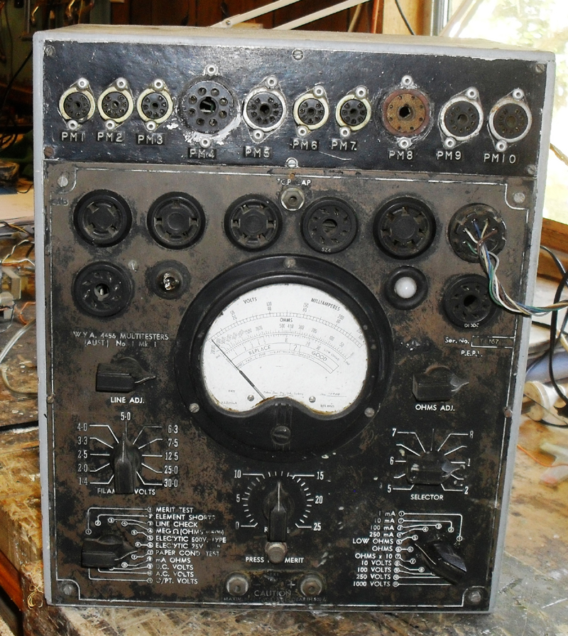
 Return to top of page · Post #: 8 · Written at 7:22:43 PM on 4 February 2017.
GTC's avatar
 GTC
 Location: Sydney, NSW
 Member since 28 January 2011
 Member #: 823
 Postcount: 6678

I noticed that Member GTC indicated he has info on the model WYA 4456

No, I referred you to member Airzone for that.


 Return to top of page · Post #: 9 · Written at 10:58:47 PM on 4 February 2017.
Brad's avatar
 Administrator
 Location: Naremburn, NSW
 Member since 15 November 2005
 Member #: 1
 Postcount: 7290

Photos uploaded to Post 7.


‾‾‾‾‾‾‾‾‾‾‾‾‾‾‾‾‾‾‾‾‾‾‾‾‾‾‾‾‾‾‾‾‾‾‾‾‾‾‾‾‾‾‾‾‾‾‾‾‾‾‾‾‾‾‾‾‾‾‾‾‾‾‾‾‾‾‾‾
A valve a day keeps the transistor away...

 
 Return to top of page · Post #: 10 · Written at 10:51:36 AM on 5 February 2017.
Stan Dean's Gravatar
 Location: Dromana, VIC
 Member since 27 December 2016
 Member #: 2025
 Postcount: 16

Thanks Brad,

Sorry GTC I missed read what you wrote. I have just sent a message to Airzone.


 Return to top of page · Post #: 11 · Written at 12:23:57 PM on 5 February 2017.
Marcc's avatar
 Location: Wangaratta, VIC
 Member since 21 February 2009
 Member #: 438
 Postcount: 5239

That is not dissimilar to the last VCT (not VCT-V) is serviced (photos available)

It is actually a Valve & Circuit Tester, as is VCT

That has had the adapter built with the extra socket as was done with the 862 military version made by Transmission Equipment.

I have the info on how that mod was done.

That is not a missing valve its a missing Vibrator.

I have sent Brad photo's to give provenance to my point. The chassis is the one on the right in the photo of two units.


Marc

Paton Valve Tester
Paton Valve Tester


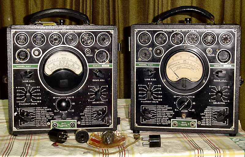
 Return to top of page · Post #: 12 · Written at 1:23:49 PM on 6 February 2017.
Stan Dean's Gravatar
 Location: Dromana, VIC
 Member since 27 December 2016
 Member #: 2025
 Postcount: 16

Thanks for the pictures Marc. It looks like you have set a high standard for my restoration.

I don't understand the requirement for a vibrator in a unit that can be plugged into the mains. Unless of course you wanted to go mobile This would mean you require a means of plugging into a battery and a change over switch from mains to battery. If I can get hold of the schematic I am sure all will be explained.

I can read on the vibrator in your unit the number 13933 I guess this is the part number.
I did find in the top of the case a battery holder that takes 3. "D" cells that I will have to identify what they were used for
Regards Stan


 Return to top of page · Post #: 13 · Written at 2:54:22 PM on 6 February 2017.
Kakadumh's Gravatar
 Location: Darlington, WA
 Member since 30 March 2016
 Member #: 1897
 Postcount: 183

Stan,

You are Not wrong re Marc's high standard of restoration...makes my poor old VCT look rather seedy even though it goes OK & gets a lot of use.

The dry cells are to power the Ohms range (NOT the Meg Ohm range) and I use standard D cells and are tight fit in the clips.

On mine the mains lead terminates in a 5 pin cord socket (I think) on 3 pins being A N & E and to run the thing on 6V DC you unplug that socket & plug in another lead that has the 6V cable & alligator clips attached.

The vibrator feeds its output into the main power transformer on a separate winding which when going the 240V side of things is then alive so that's why Palec set it up with the 2 sockets.

An acquaintance of mine had a similar model but was missing the 6V socket & cable etc so he just whacked the 6V lead straight onto the 2 pins of the plug & used it like that until he got an almighty belt from the LIVE pins of the 3 pin mains plug when he had it running on 6V one day. He went of and found a suitable socket & wired it correctly after that....No idea why though !!!

There are a couple of small differences between your unit & the VCT's..

On the VCT the Top Cap socket is on the RHS where on yours it looks like a neon or indicator lamp is mounted.
I cannot quite make out what the round device is on the LHS just to the right of the lower octal socket as that spot on the VCT is where the Neon fault/test indicator for Paper capacitors is mounted.

Quite a neat add on bit for the additional valve sockets with yours though so would make it more versatile than the VCT as is.

Lindsay


 Return to top of page · Post #: 14 · Written at 3:51:20 PM on 6 February 2017.
Stan Dean's Gravatar
 Location: Dromana, VIC
 Member since 27 December 2016
 Member #: 2025
 Postcount: 16

Good info Lindsay,

The hint that the output from the vibrator going to a winding on the transformer may be a clue. I imagine the winding would be an additional primary winding and the alternating output from the vibrator would be stepped up to give the required output voltages, but of course being part of the same transformer the normal 240v primary would then become a form of secondary winding

Marc was correct when he said the extra sockets were a military thing. When I was having a closer look I found the D.D stamp covered in the grime, and yes the top cap on mine is on the top of the panel and it has "on" light located where the top cap is on the picture


Stan


 Return to top of page · Post #: 15 · Written at 4:56:36 PM on 6 February 2017.
Marcc's avatar
 Location: Wangaratta, VIC
 Member since 21 February 2009
 Member #: 438
 Postcount: 5239

The VCT-V has a flying lead with a UX-5 valve base plug. 2 pins 6VDC in the rest N,A, & E. That has a metal cap on both it and the socket so got nobbled swiftly.

I left the DC connected and rewired the plug (only had one with it). I then let in a IEC socket in the battery box: Much happier and I have a plague of IEC patch cables.

The 6V is into a separate winding I did refit mine & it works. Watch the caps on the vibrator; these things kill them I often use line caps as vibrators produce spikes & back EMF, just like a Kettering ignition. Kettering ignitions can destroy radios. Hence the "spark plate" in early car radios.

I can photograph if required? I am getting suspicious that the VCT & it have common wiring. Yours has been got at as the two caps on the board look new: If not and they're paper, be rid of them.

The interesting thing with the big 2 μF block cap in mine which is the DC filter and probably paper, I tested it, the other one and a stray one of the same type & they failed to leak, so they stayed put.

Marc


« Back · 1 · Next »
 You need to be a member to post comments on this forum.

Sign In

Username:
Password:
 Keep me logged in.
Do not tick box on a computer with public access.