
Vintage Telephones
Forum home - Go back to Vintage Telephones
|
AWA 400 Wall Telephone Low Volume
|
|
|
« Back ·
1 ·
Next »
|
|
|
Return to top of page · Post #: 1 · Written at 11:51:14 AM on 3 April 2025.
|
|
|
|
Location: Sydney, NSW
Member since 20 March 2025 Member #: 2720 Postcount: 39 |
|
Hi, |
|
|
Return to top of page · Post #: 2 · Written at 1:08:27 PM on 3 April 2025.
|
|

|
Location: Melbourne, VIC
Member since 20 September 2011 Member #: 1009 Postcount: 1263 |
|
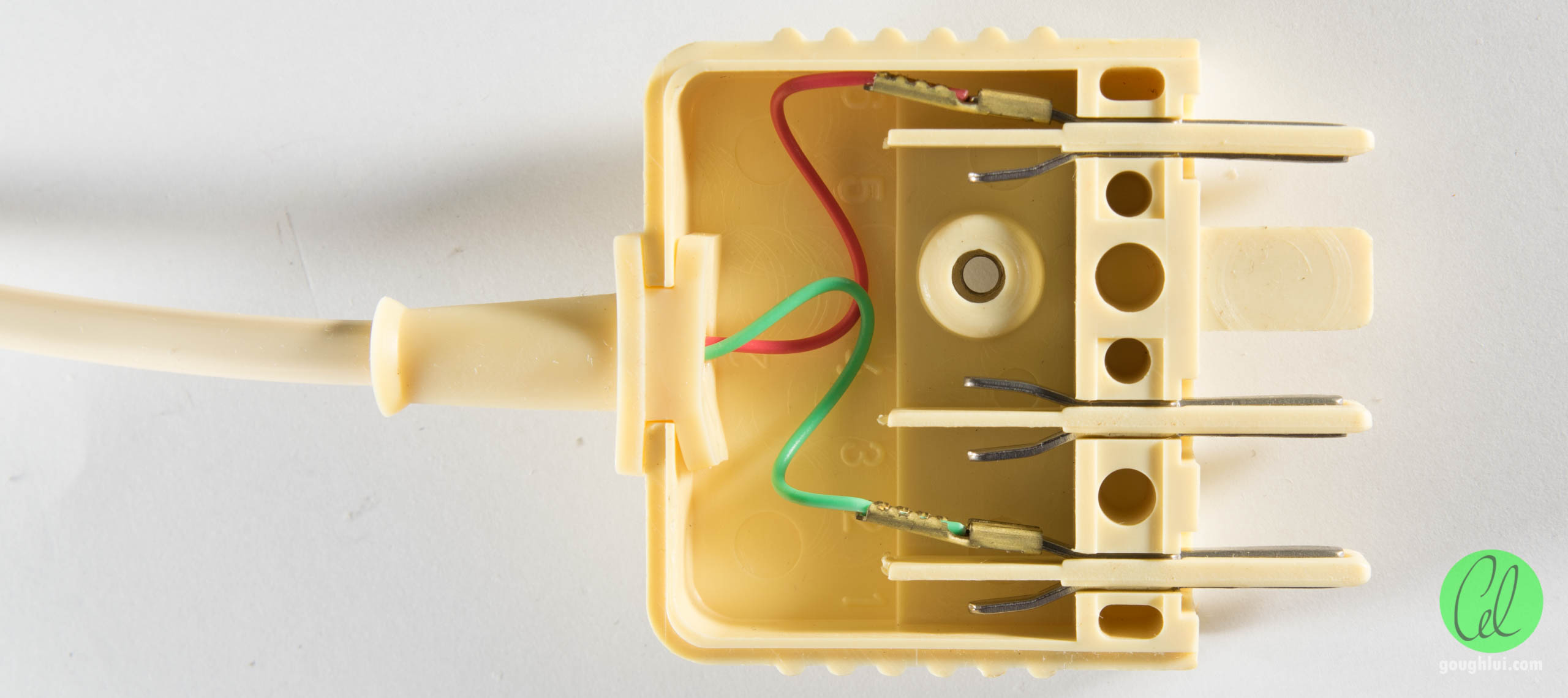
See the terminal block for line connections: |
|
|
Return to top of page · Post #: 3 · Written at 6:05:01 PM on 3 April 2025.
|
|
|
|
Location: Sydney, NSW
Member since 20 March 2025 Member #: 2720 Postcount: 39 |
|
Yes there is a circuit diagram inside 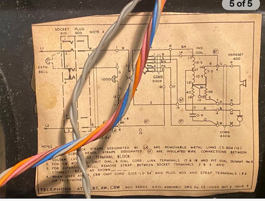 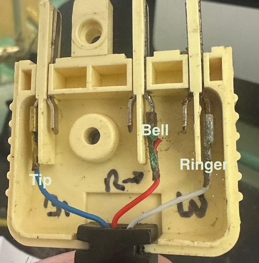 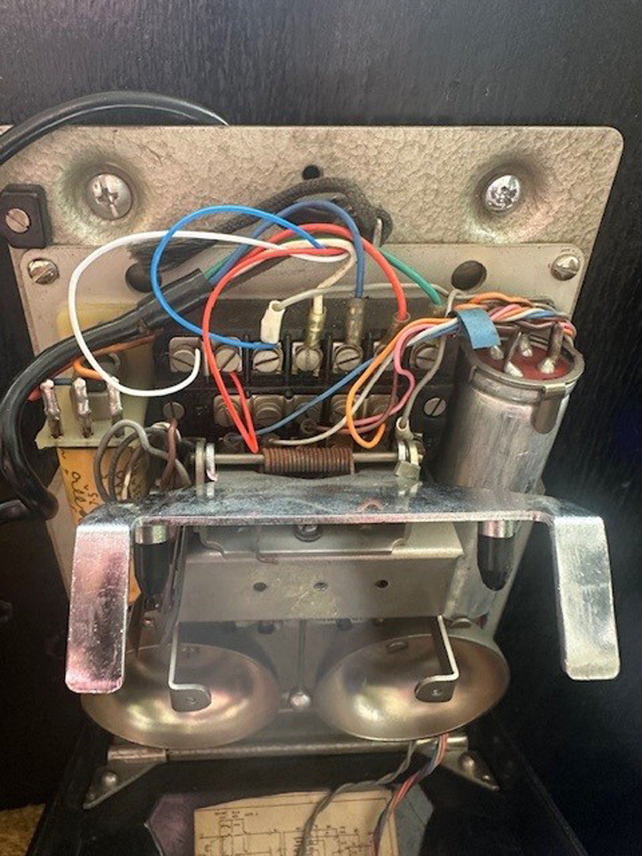 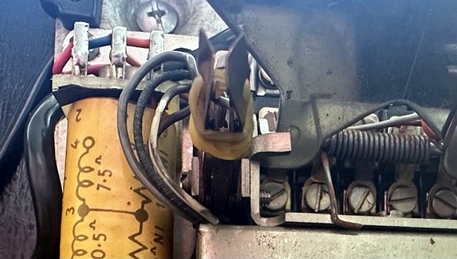 |
|
|
Return to top of page · Post #: 4 · Written at 7:26:55 PM on 3 April 2025.
|
|
|
|
Location: Melbourne, VIC
Member since 20 September 2011 Member #: 1009 Postcount: 1263 |
|
The two centre wires in a RJ11 connector are red & green. |
|
|
Return to top of page · Post #: 5 · Written at 7:45:32 PM on 3 April 2025.
|
|
|
|
Location: Sydney, NSW
Member since 20 March 2025 Member #: 2720 Postcount: 39 |
|
Your attached link of the 605 plug with red and green wires matches the original 605 plug on my phone, each wire connected to the prongs at each end of the plug but my phone has an additional red wire connecting to the middle prong, which confirms it does not need to be used/ connected |
|
|
Return to top of page · Post #: 6 · Written at 8:04:55 PM on 3 April 2025.
|
|
|
|
Location: Sydney, NSW
Member since 20 March 2025 Member #: 2720 Postcount: 39 |
|
Yes your update link shows a 605 plug to RJ11 convertor |
|
|
Return to top of page · Post #: 7 · Written at 5:13:16 AM on 4 April 2025.
|
|

|
Administrator
Location: Naremburn, NSW
Member since 15 November 2005 Member #: 1 Postcount: 7633 |
|
Photos uploaded to Post 3. ‾‾‾‾‾‾‾‾‾‾‾‾‾‾‾‾‾‾‾‾‾‾‾‾‾‾‾‾‾‾‾‾‾‾‾‾‾‾‾‾‾‾‾‾‾‾‾‾‾‾‾‾‾‾‾‾‾‾‾‾‾‾‾‾‾‾‾‾ A valve a day keeps the transistor away... |
|
|
Return to top of page · Post #: 8 · Written at 11:06:12 AM on 4 April 2025.
|
|
|
|
Location: Melbourne, VIC
Member since 20 September 2011 Member #: 1009 Postcount: 1263 |
|
On the 600 series plug the white wire goes to terminal #2. The photo shows it going to terminal #1. The corrosion on the red & green wires may be a problem. |
|
|
Return to top of page · Post #: 9 · Written at 2:47:53 PM on 4 April 2025.
|
|
|
|
Location: Sydney, NSW
Member since 20 March 2025 Member #: 2720 Postcount: 39 |
|
I’ve done a bit of wire switching and cleaning to see if there’s any difference, handset and tip and ring wires, no change at all. |
|
|
Return to top of page · Post #: 10 · Written at 3:55:45 PM on 4 April 2025.
|
|
|
|
Location: Sydney, NSW
Member since 20 March 2025 Member #: 2720 Postcount: 39 |
|
I think I’ve figured it out, I don’t want to speak too soon though. |
|
|
Return to top of page · Post #: 11 · Written at 4:13:25 PM on 4 April 2025.
|
|
|
|
Location: Melbourne, VIC
Member since 20 September 2011 Member #: 1009 Postcount: 1263 |
|
You can easily tell if the hook switch is not working by using a test lead with alligator clips between terminals #1 - #16 and #11 - #15. |
|
|
Return to top of page · Post #: 12 · Written at 4:31:32 PM on 4 April 2025.
|
|
|
|
Location: Sydney, NSW
Member since 20 March 2025 Member #: 2720 Postcount: 39 |
|
Schematics, I have no experience in understanding them unfortunately. |
|
|
Return to top of page · Post #: 13 · Written at 5:09:03 PM on 4 April 2025.
|
|
|
|
Location: Sydney, NSW
Member since 20 March 2025 Member #: 2720 Postcount: 39 |
|
Actually it can be seen in my third photo, left hand side, directly under the conical plunger that pushes the contacts apart, in-between the longer contacts there are 2 internal contacts, left hand side seems to affect handset if not always touching, mine has slight outward bend |
|
|
Return to top of page · Post #: 14 · Written at 6:05:51 PM on 6 April 2025.
|
|
|
|
Administrator
Location: Naremburn, NSW
Member since 15 November 2005 Member #: 1 Postcount: 7633 |
|
Photo (#4) uploaded to Post 3. ‾‾‾‾‾‾‾‾‾‾‾‾‾‾‾‾‾‾‾‾‾‾‾‾‾‾‾‾‾‾‾‾‾‾‾‾‾‾‾‾‾‾‾‾‾‾‾‾‾‾‾‾‾‾‾‾‾‾‾‾‾‾‾‾‾‾‾‾ A valve a day keeps the transistor away... |
|
|
« Back ·
1 ·
Next »
|
|
|
You need to be a member to post comments on this forum.
|
|
Sign In
Vintage Radio and Television is proudly brought to you by an era where things were built with pride and made to last.
DISCLAIMER: Valve radios and televisions contain voltages that can deliver lethal shocks. You should not attempt to work on a valve radio or other electrical appliances unless you know exactly what you are doing and have gained some experience with electronics and working around high voltages. The owner, administrators and staff of Vintage Radio & Television will accept no liability for any damage, injury or loss of life that comes as a result of your use or mis-use of information on this website. Please read our Safety Warning before using this website.
WARNING: Under no circumstances should you ever apply power to a vintage radio, television or other electrical appliance you have acquired without first having it checked and serviced by an experienced person. Also, at no time should any appliance be connected to an electricity supply if the power cord is damaged. If in doubt, do not apply power.
Shintara - Keepin' It Real · VileSilencer - Maintain The Rage