Vintage Telephones
Forum home - Go back to Vintage Telephones
|
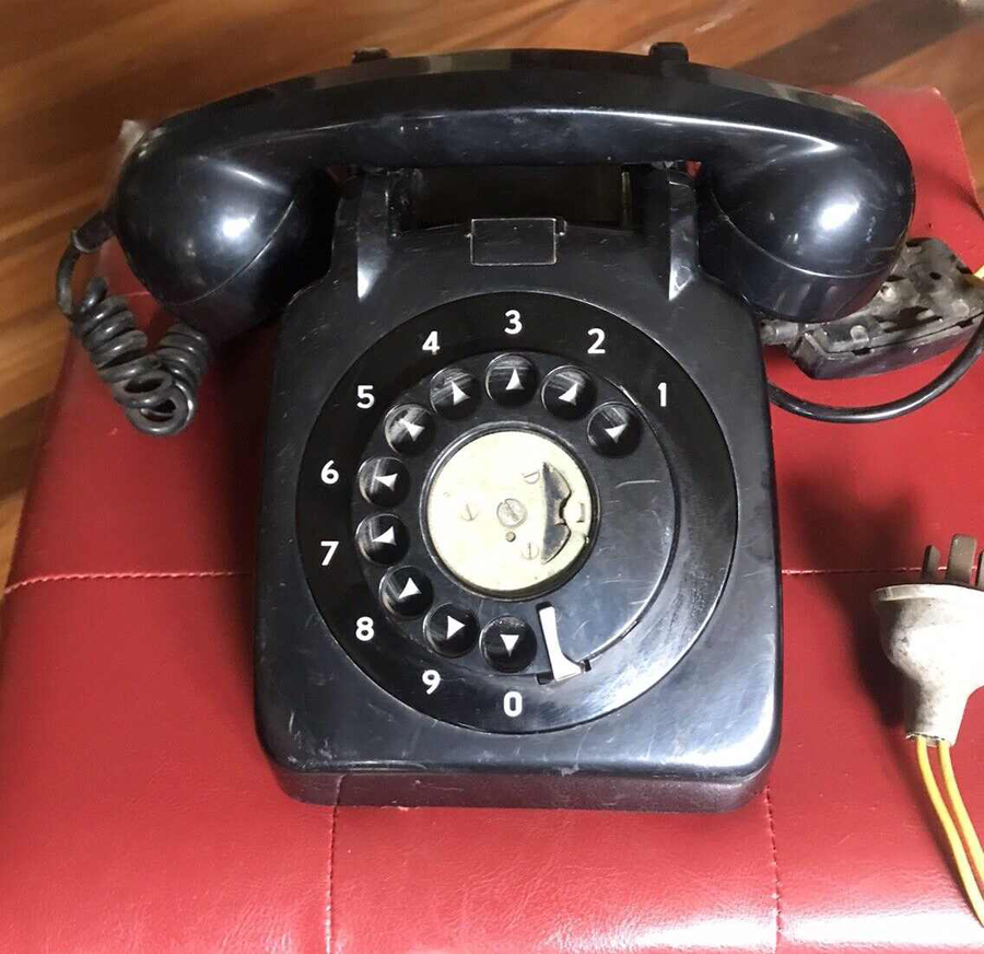
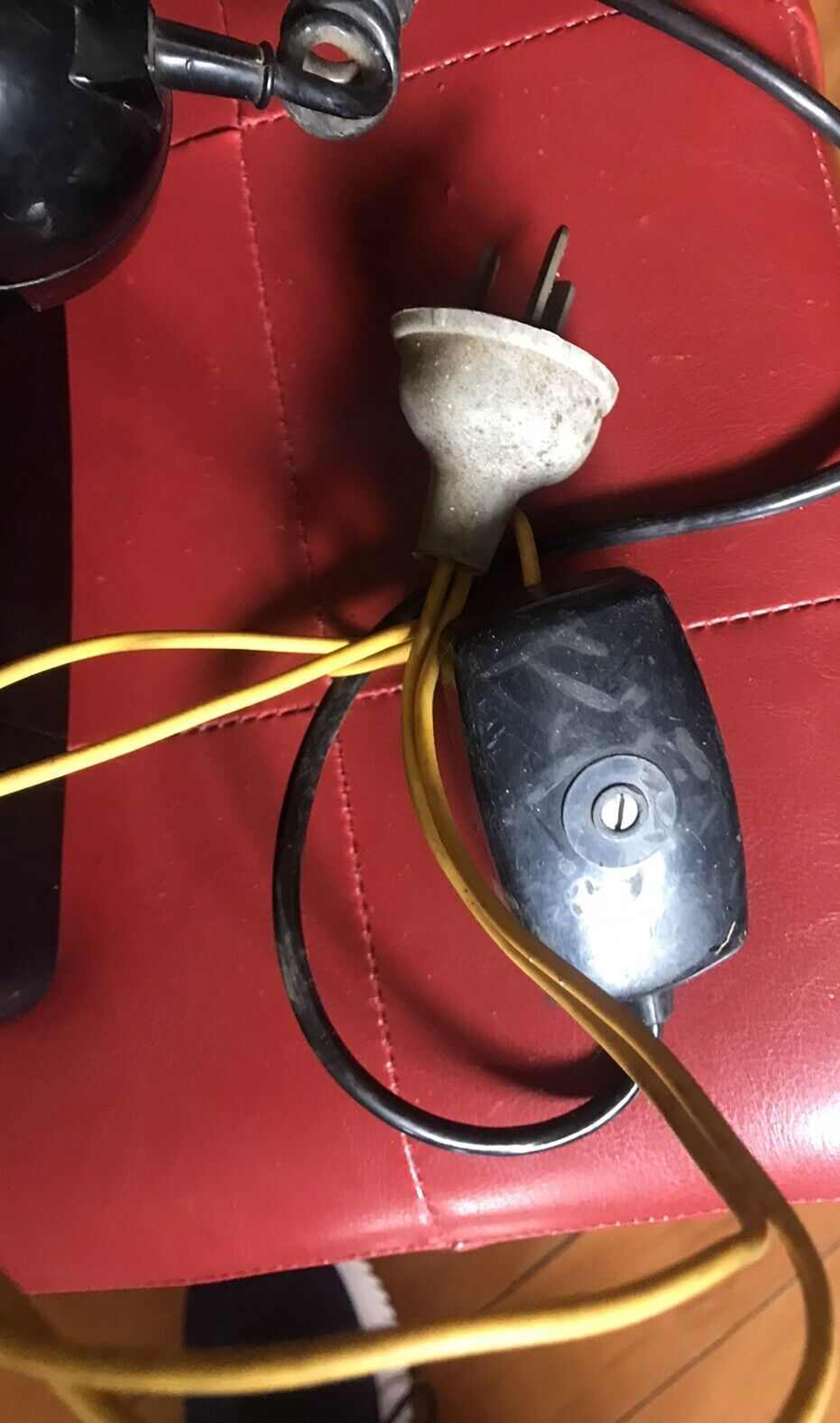
I have heard about this before but this is the first time I have seen photographic evidence.
|
|
|
« Back ·
1 ·
Next »
|
|
|
Return to top of page · Post #: 1 · Written at 7:00:06 PM on 21 August 2022.
|
|
|
|
Location: Canberra, ACT
Member since 24 April 2012 Member #: 1136 Postcount: 168 |
|
Over the years there have been reports in tech literature of subscribers adding various odd phones they have acquired as extensions on an existing PMG/Telecom service. One of the tasks assigned to staff at an auto exchange was to measure the capacitance on a subs line to see if it more than expected for the number of phones connected. If just one phone was connected the value should have been in the range of 1.5 to 2.2μF but if a subscriber had plugged in an unauthorised second phone then the value would be doubled. The PMG/Telecom were always chasing revenue for extension phones and turn up at the door of any scriber they detected as having more phones than they were paying for. The other problem was that a 'resourceful' subscriber would adapt a GPO plug and socket to connect the extra phone which was very dangerous for all concerned. A recent item on eBay provided proof that this did happen. I wonder if the item came from a 'deceased estate'.   |
|
|
Return to top of page · Post #: 2 · Written at 7:36:05 PM on 21 August 2022.
|
|
|
|
Location: Belrose, NSW
Member since 31 December 2015 Member #: 1844 Postcount: 2634 |
|
It was possible, using the jumpers in the 1st phone on the line and the extra circuits on the standard wall plug and socket, to wire the extension bells through the "master" phone. In this way, other phones on the extension would not tinkle when you were dialing, and the exchange would only see one phone. |
|
|
Return to top of page · Post #: 3 · Written at 8:11:21 PM on 21 August 2022.
|
|
|
|
Location: Hill Top, NSW
Member since 18 September 2015 Member #: 1801 Postcount: 2205 |
|
Yeah, that capacitor bypass trick was pretty well known. |
|
|
Return to top of page · Post #: 4 · Written at 11:00:45 PM on 22 August 2022.
|
|
|
|
Administrator
Location: Naremburn, NSW
Member since 15 November 2005 Member #: 1 Postcount: 7556 |
|
Photos uploaded. ‾‾‾‾‾‾‾‾‾‾‾‾‾‾‾‾‾‾‾‾‾‾‾‾‾‾‾‾‾‾‾‾‾‾‾‾‾‾‾‾‾‾‾‾‾‾‾‾‾‾‾‾‾‾‾‾‾‾‾‾‾‾‾‾‾‾‾‾ A valve a day keeps the transistor away... |
|
|
Return to top of page · Post #: 5 · Written at 7:01:14 AM on 23 August 2022.
|
|
|
|
Location: Toongabbie, NSW
Member since 19 November 2015 Member #: 1828 Postcount: 1380 |
|
Wow! |
|
|
Return to top of page · Post #: 6 · Written at 7:44:26 AM on 23 August 2022.
|
|
|
|
Location: Latham, ACT
Member since 21 February 2015 Member #: 1705 Postcount: 2217 |
|
Seen this many times when working for Telecom . I believe its natural selection in action, if you remove the signs lol the problem will eventually not exist. |
|
|
Return to top of page · Post #: 7 · Written at 8:37:17 PM on 23 August 2022.
|
|
|
|
Location: Sydney, NSW
Member since 28 January 2011 Member #: 823 Postcount: 6886 |
|
Photos uploaded. |
|
|
Return to top of page · Post #: 8 · Written at 10:11:52 PM on 23 August 2022.
|
|
|
|
Location: Canberra, ACT
Member since 24 April 2012 Member #: 1136 Postcount: 168 |
|
Thanks Brad for up-loading the photos but you have doubled up on the first photo. The second photo gave a better view of the way the plug had been wired to the connection block. However I think that the readers have grasped how dangerous the configuration was. |
|
|
Return to top of page · Post #: 9 · Written at 10:50:16 PM on 23 August 2022.
|
|
|
|
Administrator
Location: Naremburn, NSW
Member since 15 November 2005 Member #: 1 Postcount: 7556 |
|
All fixed. ‾‾‾‾‾‾‾‾‾‾‾‾‾‾‾‾‾‾‾‾‾‾‾‾‾‾‾‾‾‾‾‾‾‾‾‾‾‾‾‾‾‾‾‾‾‾‾‾‾‾‾‾‾‾‾‾‾‾‾‾‾‾‾‾‾‾‾‾ A valve a day keeps the transistor away... |
|
|
Return to top of page · Post #: 10 · Written at 9:22:50 AM on 27 August 2022.
|
|
|
|
Location: Canberra, ACT
Member since 24 April 2012 Member #: 1136 Postcount: 168 |
|
The old phone has arrived so I have been able to examine it. The case was badly scratched but fortunately the internal components (that I wanted) were in good condition. On checking the line wiring I found that it had been connected between Neutral and Earth in the three-pin plug which might have provided some protection had the phone been plugged into a real GPO. However if the GPO had Active and Neutral transposed then the result would have been fireworks and lots of 'magic smoke'. |
|
|
Return to top of page · Post #: 11 · Written at 3:49:35 PM on 27 August 2022.
|
|
|
|
Location: NSW
Member since 10 June 2010 Member #: 681 Postcount: 1377 |
|
Had a neighbour back in the '60s who rigged up an extension speaker for his radiogram using 240VAC plug and socket and a length of two core flex. Took a fair bit of diplomatic explaining to convince him that this was not a good idea. |
|
|
Return to top of page · Post #: 12 · Written at 9:46:41 PM on 27 August 2022.
|
|
|
|
Location: Sydney, NSW
Member since 28 January 2011 Member #: 823 Postcount: 6886 |
|
When I was aged 5 or 6, my father borrowed a neighbour's electric mower while our Atco was having its blades sharpened. The neighbour had attached a female 3-pin Bakerlite socket to the wooden handle of the mower and used a suicide cable to connect to an extension cord. I vividly recall my father asking me why it was a very bad idea. |
|
|
Return to top of page · Post #: 13 · Written at 5:50:51 AM on 28 August 2022.
|
|
|
|
Administrator
Location: Naremburn, NSW
Member since 15 November 2005 Member #: 1 Postcount: 7556 |
|
Document uploaded to Post 10. ‾‾‾‾‾‾‾‾‾‾‾‾‾‾‾‾‾‾‾‾‾‾‾‾‾‾‾‾‾‾‾‾‾‾‾‾‾‾‾‾‾‾‾‾‾‾‾‾‾‾‾‾‾‾‾‾‾‾‾‾‾‾‾‾‾‾‾‾ A valve a day keeps the transistor away... |
|
|
« Back ·
1 ·
Next »
|
|
|
You need to be a member to post comments on this forum.
|
|

Sign In

Vintage Radio and Television is proudly brought to you by an era where things were built with pride and made to last.
DISCLAIMER: Valve radios and televisions contain voltages that can deliver lethal shocks. You should not attempt to work on a valve radio or other electrical appliances unless you know exactly what you are doing and have gained some experience with electronics and working around high voltages. The owner, administrators and staff of Vintage Radio & Television will accept no liability for any damage, injury or loss of life that comes as a result of your use or mis-use of information on this website. Please read our Safety Warning before using this website.
WARNING: Under no circumstances should you ever apply power to a vintage radio, television or other electrical appliance you have acquired without first having it checked and serviced by an experienced person. Also, at no time should any appliance be connected to an electricity supply if the power cord is damaged. If in doubt, do not apply power.
Shintara - Keepin' It Real · VileSilencer - Maintain The Rage
