|
Triple dial LM Ericsson device - need help to identify
|
|
« Back ·
1 ·
Next »
|
|
|

|
Location: Carupano, VE
Member since 9 December 2014
Member #: 1664
Postcount: 5
|
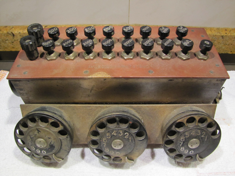
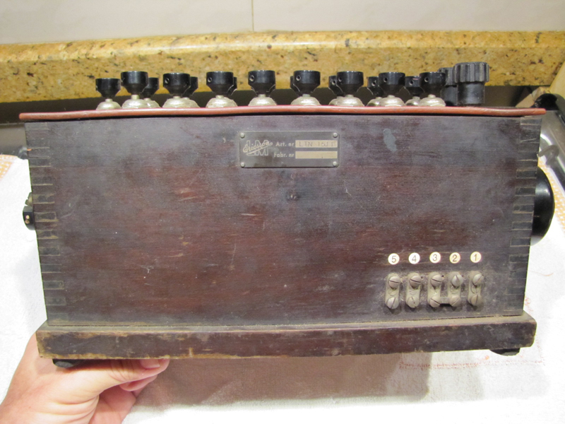
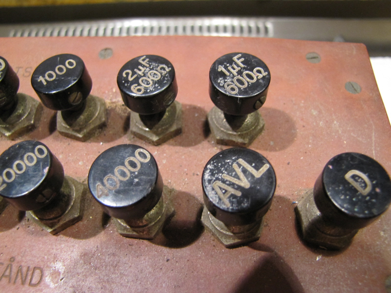
Hi! I need your help to try to identify MFG year and what exactly it is for........
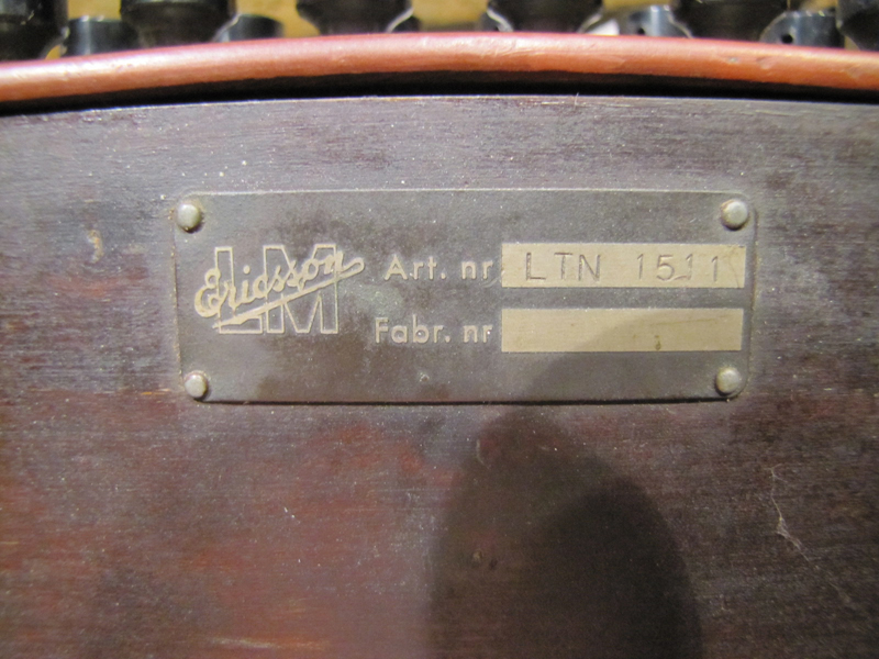
At the back, there is a small identification plate with LM Ericsson logo and article number 15.11. I've been looking in the internet for hours and can not find anything.
|
|
|
|
|

|
Location: Sydney, NSW
Member since 28 January 2011
Member #: 823
Postcount: 6956
|
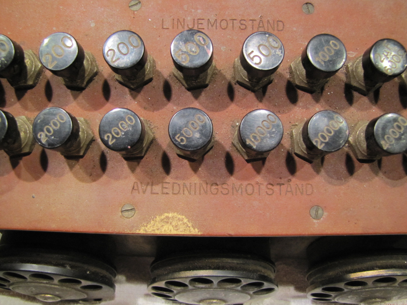
Looks to be test equipment.
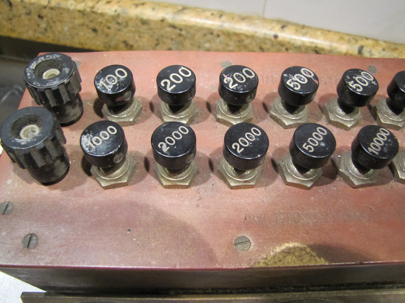
The English translation of the Swedish 'linje motstand' is line resistance and 'avlednings motstand' is leakage resistance.
Presumably the buttons allowed the user to increase or reduce resistance for the line under test.
|
|
|
|
|
|
Location: Canberra, ACT
Member since 24 April 2012
Member #: 1136
Postcount: 176
|
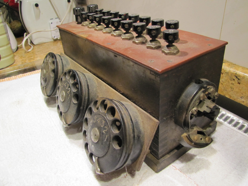
Definitely test equipment used at an exchange and from the markings on the buttons I would think that it was for testing how well an SxS selector or a Crossbar register could follow dial pulses over a high resistance and/or capacitance line (or ‘leaky’ line as suggested by GTC). The combination of resistance and capacitance on a line will distort dial pulses to the point where the selector/register would not count the number of pulses correctly. Why there would be three dials I am not sure unless they are set to run at different rates; i.e. 8pps, 10pps and 12pps. This would allow for testing to simulate dialling from a phone that had a dial that was out of adjustment. A ‘standard’ dial ran at 10pps although some Ericsson equipment used 20pps. The three-pin connector on the left side would allow a test phone to be plugged in.
Judging from the type of dials fitted, the unit could date from 1948/9 to about 1965/6 which was the period that type of dial was in normal use.
|
|
|
|
|
|
|
Location: Canberra, ACT
Member since 24 April 2012
Member #: 1136
Postcount: 176
|
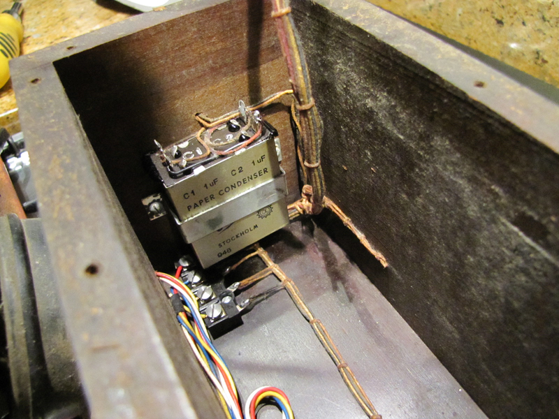
An additional thought, the ‘948’ on the ‘PAPER CONDENSER’ capacitor may stand for September 1948. The waxed cotton insulation on the internal wiring would also indicate 1940s construction. However I see that the leads from the dials have 1950/60s plastic insulation. Looking at the way the three dials are mounted, it is not the same material as the wooden case so I think that they may have been added later as a modification.
Still a nice item to have in your collection.
|
|
|
|
|
|
Location: Silver City WI, US
Member since 10 May 2013
Member #: 1340
Postcount: 977
|
..the selector/register would not count the number of pulses correctly
I suppose crossbar would have to have a way to decode and store the incoming number, what device did they use they count the pulses?
It would also have to store, analyse and determine if the number was local or to another area code, then execute call connection?
Like when making an international from Australia via OTC in the 1970s one would hear the stored number forwarded in a packet of 10 or so standard MF tones. You would also hear this on local calls with some GTE exchanges in the 'states in the 1970s & 80's but not on others like Honolulu and Manila which were also GTE.
|
|
|
|
|
|
|
Location: Canberra, ACT
Member since 24 April 2012
Member #: 1136
Postcount: 176
|
Re Crossbar counting dial pulses; it depended on the system and the size of the switch. On the small 25-line ARD520 (which is the only Crossbar switch that I have 'played' with) there was a relay register/marker that counted the pulses and then marked a connection via a Crossbar switch matrix. (There is a circuit diagram for one of these relay registers floating about on the Web and I will post the link when I find it again.)
On the larger switches (for which I have only read the instruction and training manuals) the pulses were counted on either a relay register or a Crossbar switch matrix. I understand that later versions had an electronic register.
The clever thing about the Crossbar was that it set up the end-to-end connection as soon as a digit was entered into the register and was very fast in operation so that generally only two registers were required for a system switching thousands of lines. Communication between stages in a switch and between exchanges was done by VF tones and when a dial pulse went into a register it was encoded as a VF tone. There were other tones that were used to signal the progress of the connection as it was set up through the various stages. These may be what you heard on calls via OTC.
|
|
|
|
|
|
|
Location: Silver City WI, US
Member since 10 May 2013
Member #: 1340
Postcount: 977
|
If these (electromechanical) registers could accept 20pps they must have not have been of the stepping design which was limited to 10pps. Maybe like a relay version of a cascaded flip-flop register?
|
|
|
|
|
|
|
Location: Canberra, ACT
Member since 24 April 2012
Member #: 1136
Postcount: 176
|
The original Strowger/Automatic Electric two-motion selector as used in a SxS switch had the inherent limitation that it could not reliably operate faster than 10pps due to the mass of the mechanism. It was designed to follow the pulses from the dial and the dial itself had an inbuilt delay (‘inter-digit pause’) to ensure a minimum time period between each digit dialled. Each group selector stepped up to level corresponding to the digit dialled and then was driven across the bank contacts to locate the next free selector. The final selector stepped up to level corresponding to the second last digit dialled and then moved across the bank contact corresponding to the last digit dialled. Other companies such as ATM (British affiliate of Automatic Electric), Coventry Electric and Siemens made their own versions of the two-motion selector which were mechanically better than the AE unit. The Siemens No: 16 could operate faster than the Strowger/Automatic Electric design but 10pps remained the standard speed. The British GPO No: 8, No: 10 and No: 12 dials were based on a Siemens designed dial from 1921 and all operated at 10pps. The corresponding Automatic Electric dial was the No: 24.
In the early 1920s the ATM developed the ‘Director’ system as a way of interconnecting multiple exchanges in large cities. (This was to compete with the US Western Electric ‘Panel’ system.) The ‘Director’ was a small relay logic unit which counted the first three digits dialled and then translated this ‘address’ to select a junction line (US term – ‘trunk’) to the required exchange. The following digits were then sent via a Relay Set Repeater to control two-motion selectors in the distant exchange. Again it was all run at 10pps.
In British telephone exchanges during the 1930s there was an improved version of the two-motion selector known as the 2000-type and in the 1950s the SE50 selector but these still operated at 10pps.
Some later versions of SxS switches, mainly smaller PAX and PABX units, used relay or uniselector registers to count the dial pulses and then the selectors made the speech connection. This was called ‘by-pass switching’.
For its automatic switching, Western Electric developed the A7 ‘Rotary’ system in 1912 and the ‘Panel’ system in 1918. Both of these had a very different design of selector from the SxS switch and both systems used a register to count the digits dialled. The register then controlled the selectors which were power driven and therefore operated faster than an SxS switch. However the WE dial still operated at 10pps but as it did not have an inbuilt delay (because the register did not require an ‘inter-digit pause’), it was theoretically faster for dialling a phone number than an AE dial. WE marketing at the time claimed a time saving of approximately 10 minutes in a year!
Other companies had their own designs such as the Stromberg-Carlson ‘X-Y’ selector and the Ericsson ‘500-point’ selector. As far as I know both these systems used registers to control the selectors. AE also had a ‘rotary relay’ selector as an alternative to the usual two-motion selector but I do not know if this system used a register. On small PAX and PABX many companies used cheaper uniselectors rather than two-motion selectors. Uniselectors can operate faster than 10pps but again these all used standard telephones with a 10pps dial.
Around 1910, Betulander in Sweden developed an all-relay system to get around what he saw as the limitations of the Strowger selector and SxS design of the time. (This was before the Keith Line-switch was introduced and the Strowger system still used 3-wire dialling.) A relay matrix was used to perform the same logical switching function of the Strowger selector and a form of register, called a ‘recorder/marker’ counted the dial pulses. Initially Betulander used a three or four lever ‘dial’ similar to the Lorimar design but later he changed to a ‘standard’ 10pps dial design. In 1918 WE developed the crossbar switch but apparently did not know to use it effectively. As soon as Betulander became aware of this switch he used it in place of the relay matrix but still retained the relay recorder/marker. An improved version of this Betulander system was the basis of the Ericsson crossbar system that eventually replaced SxS in many places. However all-relay systems similar to the early Betulander system where made by various companies such as Marconi and GEC in Britain and Northern Electric in the USA and Canada.
AE and some other US companies also made all-relay systems but from what information I have these seem to have been closer to using chains of relays to emulate uniselectors rather than the Betulander matrix concept. Again all these worked with standard automatic telephones fitted with 10pps dials.
In the late 1950s WE and Ericsson started to develop electronic switches which were controlled by electronic registers. WE designed the ESS series which initially used a lever dial like the old Lorimar design. Later they used rotary dials and then push-button ‘dials’. Ericsson initially developed a hybrid system using crossbar switches. I think that it was this Ericsson system that could work with a dial running at 20pps. However Ericsson also developed their own design of push-button ‘dial’ that was used on PABX units well before the WE push-button ‘dial’ appeared.
From the late 1960s push-button ‘dials’ became more common but these were still decadic and operated at 10pps regardless of how fast you pushed the buttons. Once DTMF signalling became the norm the digits were received at the switch by an electronic register so ‘dialling’ was as fast as the chip in the phone could generate the tone pairs; the old 10pps standard became meaningless.
|
|
|
|
|
|
|
Location: Silver City WI, US
Member since 10 May 2013
Member #: 1340
Postcount: 977
|
Thanks Relayautomatic, a lot of history to digest there but I find it intriguing. Seems the challenge of auto connection sparked many solutions in the golden-age of invention. I'm largely ignorant of Telco-tech and had no idea of the 1918 W.E. 'Panel' and 'Rotary' systems for instance: so I just find a surprising old film online of a 'Panel' unit operating, with those bugs riding up and down a large terminal grid wow, would have been expensive to implement, but I suppose price was no object for the Bell/WE System - a vertically-integrated monopoly that would subsidize its sole manufacturer--a luxury not afforded the BPO/ATM System where hardware was put out on bid to private ATM or others? So which system was really more Capitalist, one could ponder?
The US Govt was fond of taking 'antitrust' action on perceived monopolies, like killing W.E.'s foreign ventures after they developed the 'Rotary' switch in Belgium. The thinking would be the danger of subsidies from the US monopoly hurting private manufacturers. Same action taken on Western Electric movie sound equipment in the 1940s. But the government's biggest surprise was yet to come: Perhaps they felt it coming; strange Ads started appearing in 1974 in influential Fortune magazine like the one with a picture of 19th century British philosopher John Stuart Mill saying "London would be better served if there was only one Gas company". The axe fell just 10 years later with the break-up. So with Western Electric finally destroyed, what gear was the local Telco now using? A friend on the inside 10 years ago said they were using lowest-bid imported NEC and Nortel-Canada systems.
|
|
|
|
|
|
|
Location: Sydney, NSW
Member since 28 January 2011
Member #: 823
Postcount: 6956
|
RA: where were you when I had to cram for my exams? 
I forgot most of this stuff the minute the course was over.
|
|
|
|
|

|
Location: Perth, WA
Member since 19 November 2008
Member #: 381
Postcount: 240
|
|
|
|
|
|

|
Location: Canberra, ACT
Member since 23 August 2012
Member #: 1208
Postcount: 587
|
 Garyoz: Garyoz:
QUOTE: you can get a 10% discount on your Telstra bill.
..and that's after a 15% penalty for being a loyal customer or not having a choice
Maven
|
|
|
|
|

|
Location: Darlington, WA
Member since 30 March 2016
Member #: 1897
Postcount: 197
|
That old test unit brought back memories of the very early Ericsson test sets in exchanges & the 3 dials were set for different speeds...usually one at about 6 IPS one at 10 IPS & the other at 20 IPS. Quite easy to set as most exchanges had a Test Desk that could check Impulse Speed, the Mark/Space ratio as well as Count & display what digit was dialled. The dials themselves were easy to adjust using a tool to simply bend the governor arms built into the dial..each one bent the same amount as the other.As best one could judge in the field.
It was quite common in the step by step days when you installed a phone to call into the Test Desk to clear off the installation & in many sites one had to do a dial test AND if the Speed was out of spec (9-11 IPS) one had to pull the phone apart & readjust the dial speed before you could get a clearance.
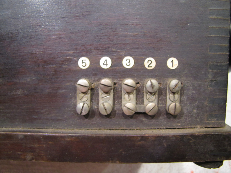
Those early Ericsson test sets did not last long as trolley mounted test sets were soon introduced & they could vary the dial speed, insert line resistance & line leakage etc. They were also fully equipped with MFC tone generators & receivers so could simulate ANY bit of gear in a Crossbar exchange. You plugged it into whatever bit of gear you were tangling with, set the digit switches to what combinations you needed to send & let it rip.
Each 1000 lines of customers was handled by a SL Marker & dependent upon expected traffic & later on actual measured traffic they could have 2 markers installed.
Lifting the handset on a customers phone called in the SL marker to allocate the customer a SR relay set (Speaking Relay set) Ericsson was good at using the first letter of many of the devices to make the name for the relay set or device... in this case SR.
That done another switching stage (RS) searched for, allocated & then switched through to the SR a Register which then supplied Dial Tone to the caller. So in that short time frame from a customer lifting a handset & getting it to their ear a lot went on in the exchange.
The caller dialled into the Reg (Register) counted using a counting chain & stored on relays in some Regs & on crossbar switches in older type exchanges.
Depending upon the number dialled the Reg could Analyse the digits & determine at what point to start switching and when the full number was dialled it would initiate a Call GV signal via the SR to start switching the call.
Each 1000 line group was switched by a GV marker and in a typical exchange of up to 10,000 lines it did most of the work but if the site was over 10,000 lines then another stage called a GVC was introduced to further expand the capacity.
When the SR hit the GV stage with a call it would interact with the Reg to work out whether the call was a local one within the exchange group OR it had to be trunked to another exchange.
If it was a local call the GV would analyse the digits it needed to determine which 1000 line group it had to switch to, then initiate the switching to another SL marker & drop off the connection & that SL marker then would receive digits necessary to switch the call to the other customer and in all cases using MFC signalling was used with what we called compelled sequence switching in that the send tones were applied forward & as soon as that next switching stage received it a "next digit" signal came back from the device the Reg was talking to & the next digit was sent forward. Thus the tones were only on for as long as needed & typically a 10 digit number could be sent in less than one second. If there was a period of heavy traffic & gear was rather busy you could tell by watching the Reg almost which stage it was that was being worked hard as the signalling chain moved along...in light traffic periods it would be rattle rattle rattle & done. In busy periods it would be more like rattle...pause, rattle pause and then all would rattle away to the end. (MFC or Multi Frequency Code used a combination of 2 tones to signify each digit or command function supplied by very stable tone generators & accepted by equally precise tone receivers.)
Once the Reg & local SL marker had set the call up the SL marker would signal back "Connect", the Reg would cause the SR to switch the voice path forward & then both the Reg & the SL marker would drop off.
The SR would provide ringing forward, ringtone back to the caller & on the called customer answering would switch the call & allow conversation between both. At the end of the call as the parties hung up a single meter pulse would be sent to calling customers Local Call Meter.
IF the call was to go beyond the local exchange the GV stage would select an outgoing relay set (FUR) which would connect to the desired exchange OR another Tandem switching stage to get access to the called party. It would switch the Reg through & drop off & then the Reg would call forward via the FUR to the called number & at that exchange the incoming side would be handled by another line relay set called an FIR. When that was seized the distant GV stage would talk to the Reg, determine which 1000 line group it needed to switch to, do the switching & call that 1000 line groups SL marker which would handle the incoming digits from the Reg, set the switching path from the FIR to the desired customer & then drop off. The FIR at the distant exchange would feed ringing forward & ring tone BACK to the calling exchange.
At the originating exchange the SR would be set in JT mode (Junction mode) which disabled the ringing function & enabled a loop forward function which held the outgoing FUR & the Reg would drop off & the call would be connected. At the end of the call as the parties cleared the SR again would meter the calling party. In the early days of STD (Subscriber Trunk Dialling) the SR & FUR could repeat multimetered pulses back to the calling party's meter to charge the call. That has since been superseded by other upgrades where the Trunk Exchanges were sent the calling party's number during the call setup process & billing done that way rather than using Multimetered pulses.
Thus an awful lot went on behind the scenes when customers started to dial out until they got a ringtone back. Usually by the time one had finished dialling there was a slight pause and BINGO Ring Tone or Busy whatever the case maybe.
At NO stage are customers across the line to be able to hear the MFC signalling as it could lead to false signalling or even fraudulent setting up of calls unlike some other systems used elsewhere in the world...USA for example.
That has now all been replaced by a fully digital switching system which is even more complex & uses an even more sophisticated signalling system called Common Channel Signalling. As that all came into being within Telstra I took a package & retired from it.
|
|
|
|
« Back ·
1 ·
Next »
|
|
You need to be a member to post comments on this forum.
|