
Vintage Gramophones and Phonographs
Forum home - Go back to Vintage Gramophones and Phonographs
|
Help needed for newbie with Philips RF780 RadioGram Repair
|
|
|
Return to top of page · Post #: 1 · Written at 10:44:21 AM on 21 September 2020.
|
|
|
|
Location: Brisbane, QLD
Member since 21 September 2020 Member #: 2441 Postcount: 5 |
|
Hi Guys/Gals, 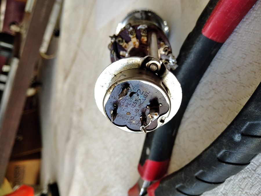 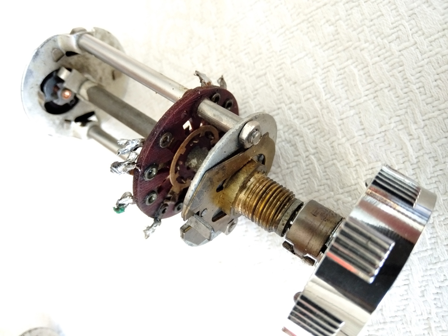 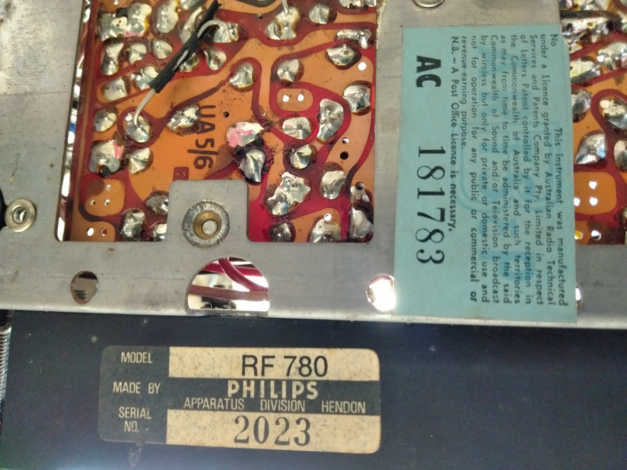 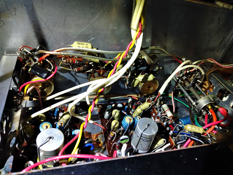 |
|
|
Return to top of page · Post #: 2 · Written at 11:03:21 AM on 21 September 2020.
|
|
|
|
Location: Belrose, NSW
Member since 31 December 2015 Member #: 1844 Postcount: 2714 |
|
I'd say you have an earth leakage. This could be anywhere in the mains side circuit, e.g. turntable mains switch, main unit switch, power cable. Only sure way to find it is by isolating things. Try unplugging the turntable mains connection first, since this is easier. |
|
|
Return to top of page · Post #: 3 · Written at 7:00:47 PM on 21 September 2020.
|
|
|
|
Location: Toongabbie, NSW
Member since 19 November 2015 Member #: 1828 Postcount: 1414 |
|
Good Luck John! |
|
|
Return to top of page · Post #: 4 · Written at 9:46:52 PM on 21 September 2020.
|
|

|
Administrator
Location: Naremburn, NSW
Member since 15 November 2005 Member #: 1 Postcount: 7643 |
|
Photos uploaded. ‾‾‾‾‾‾‾‾‾‾‾‾‾‾‾‾‾‾‾‾‾‾‾‾‾‾‾‾‾‾‾‾‾‾‾‾‾‾‾‾‾‾‾‾‾‾‾‾‾‾‾‾‾‾‾‾‾‾‾‾‾‾‾‾‾‾‾‾ A valve a day keeps the transistor away... |
|
|
Return to top of page · Post #: 5 · Written at 11:06:55 PM on 21 September 2020.
|
|

|
Location: Sydney, NSW
Member since 28 January 2011 Member #: 823 Postcount: 6964 |
|
The radiomuseum page on the RF780 has a "schematic" you can download directly. |
|
|
Return to top of page · Post #: 6 · Written at 7:08:00 AM on 22 September 2020.
|
|
|
|
Location: Toongabbie, NSW
Member since 19 November 2015 Member #: 1828 Postcount: 1414 |
|
Yep, click on the link in Ian's post. |
|
|
Return to top of page · Post #: 7 · Written at 7:10:02 AM on 22 September 2020.
|
|
|
|
Location: Toongabbie, NSW
Member since 19 November 2015 Member #: 1828 Postcount: 1414 |
|
Oh, and those power switch modules can arc over internally with about 1 poofdeenth clearance between A, N and E!!! |
|
|
Return to top of page · Post #: 8 · Written at 9:36:06 AM on 22 September 2020.
|
|
|
|
Location: Brisbane, QLD
Member since 21 September 2020 Member #: 2441 Postcount: 5 |
|
Well as you suggested Fred the power switch module interior does look a tad unwell. I'm not sure it's salvageable and I'm not sure what it's supposed to look like anyway. 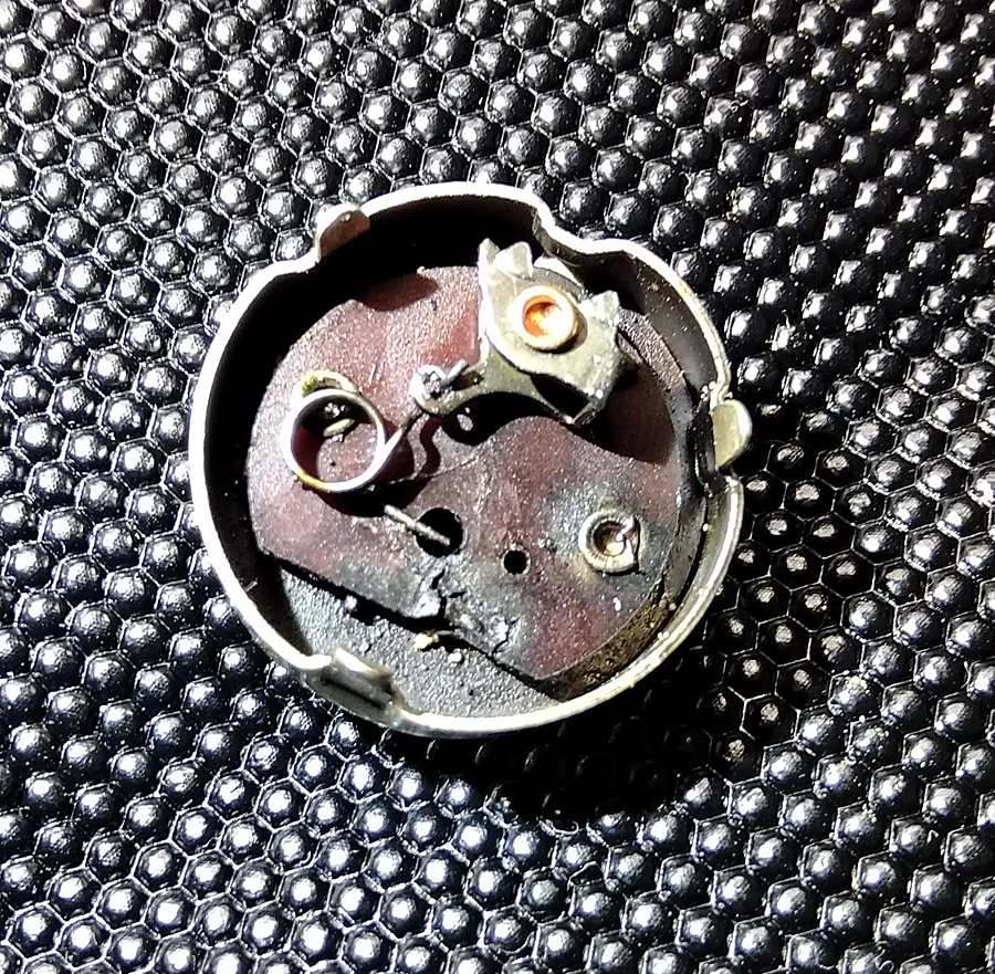 |
|
|
Return to top of page · Post #: 9 · Written at 5:11:36 PM on 22 September 2020.
|
|
|
|
Location: Toongabbie, NSW
Member since 19 November 2015 Member #: 1828 Postcount: 1414 |
|
Hi, I have grafted a different type of switch wafer onto the spindle and made sure the insulation of the mounting was to my standard. |
|
|
Return to top of page · Post #: 10 · Written at 5:15:21 PM on 22 September 2020.
|
|
|
|
Location: Sydney, NSW
Member since 28 January 2011 Member #: 823 Postcount: 6964 |
|
Well that's a first. Have never seen them attached like that. Makes them much easier to download. It's a wonder that the guy who rules over RM allows it. |
|
|
Return to top of page · Post #: 11 · Written at 8:31:48 PM on 22 September 2020.
|
|
|
|
Administrator
Location: Naremburn, NSW
Member since 15 November 2005 Member #: 1 Postcount: 7643 |
|
Photo uploaded to Post 8. ‾‾‾‾‾‾‾‾‾‾‾‾‾‾‾‾‾‾‾‾‾‾‾‾‾‾‾‾‾‾‾‾‾‾‾‾‾‾‾‾‾‾‾‾‾‾‾‾‾‾‾‾‾‾‾‾‾‾‾‾‾‾‾‾‾‾‾‾ A valve a day keeps the transistor away... |
|
|
Return to top of page · Post #: 12 · Written at 9:01:47 PM on 22 September 2020.
|
|
|
|
Location: Belrose, NSW
Member since 31 December 2015 Member #: 1844 Postcount: 2714 |
|
Those switches are made of unobtainium. They were never safe, even when new IMHO. |
|
|
Return to top of page · Post #: 13 · Written at 11:12:22 PM on 22 September 2020.
|
|
|
|
Location: Brisbane, QLD
Member since 21 September 2020 Member #: 2441 Postcount: 5 |
|
Thanks for the suggestions. I'm considering my options and will probably just bypass the switch and either turn it on at the wall or install a seperate on/off switch on the back. It would encourage me not to leave it turned on unattended anyway. |
|
|
Return to top of page · Post #: 14 · Written at 7:01:54 AM on 23 September 2020.
|
|
|
|
Location: Toongabbie, NSW
Member since 19 November 2015 Member #: 1828 Postcount: 1414 |
|
John for the moment just join the wires together (safely) and use an external switch to turn it on and off for testing. |
|
|
Return to top of page · Post #: 15 · Written at 10:49:51 AM on 24 September 2020.
|
|
|
|
Location: Brisbane, QLD
Member since 21 September 2020 Member #: 2441 Postcount: 5 |
|
Interesting story Fred. I think I'll probably end up with a seperate power switch on the cabinet (discretely), those old switches don't inspire much confidence. |
|
|
You need to be a member to post comments on this forum.
|
|
Sign In
Vintage Radio and Television is proudly brought to you by an era where things were built with pride and made to last.
DISCLAIMER: Valve radios and televisions contain voltages that can deliver lethal shocks. You should not attempt to work on a valve radio or other electrical appliances unless you know exactly what you are doing and have gained some experience with electronics and working around high voltages. The owner, administrators and staff of Vintage Radio & Television will accept no liability for any damage, injury or loss of life that comes as a result of your use or mis-use of information on this website. Please read our Safety Warning before using this website.
WARNING: Under no circumstances should you ever apply power to a vintage radio, television or other electrical appliance you have acquired without first having it checked and serviced by an experienced person. Also, at no time should any appliance be connected to an electricity supply if the power cord is damaged. If in doubt, do not apply power.
Shintara - Keepin' It Real · VileSilencer - Maintain The Rage