
Vintage Gramophones and Phonographs
Forum home - Go back to Vintage Gramophones and Phonographs
|
General Electric RS17T1 Stereogram
|
|
|
« Back ·
1 ·
Next »
|
|
|
Return to top of page · Post #: 1 · Written at 5:37:08 PM on 3 May 2015.
|
|
|
|
Location: Canberra, ACT
Member since 23 August 2012 Member #: 1208 Postcount: 587 |
|
I've been given the guts of a GE RS17T1 stereogram that has been in a shed since the cabinet was "re-purposed" for a TV table about twenty years ago. The owner was an electrician and tells me everything works. The turntable is a Garrard 3000 record-changer, the amp is solid-state but all discrete components, and the tuner is some sort of coil tuner with press-button selectors. Two twin-cone 12" Rola speakers that look to be in very good condition. Output is supposed to be 10w "undistorted". |
|
|
Return to top of page · Post #: 2 · Written at 7:00:58 PM on 3 May 2015.
|
|

|
Location: Sydney, NSW
Member since 28 January 2011 Member #: 823 Postcount: 6964 |
|
Pity the cabinet is gone; it was good looking model: |
|
|
Return to top of page · Post #: 3 · Written at 8:35:51 PM on 3 May 2015.
|
|

|
Location: Melbourne, VIC
Member since 20 September 2011 Member #: 1009 Postcount: 1267 |
|
Kevin Chant has a version from the 1967 JR Transistor Group 4 book: |
|
|
Return to top of page · Post #: 4 · Written at 11:03:40 PM on 3 May 2015.
|
|
|
|
Location: Canberra, ACT
Member since 23 August 2012 Member #: 1208 Postcount: 587 |
|
Yes, that's the PDF that I have - but notice that it begins halfway through a sentence so clearly something is missing. |
|
|
Return to top of page · Post #: 5 · Written at 10:47:57 PM on 5 May 2015.
|
|
|
|
Location: Canberra, ACT
Member since 23 August 2012 Member #: 1208 Postcount: 587 |
|
After basic checks and inspections I hooked this up on the bench. It delivers a really impressive tone from an AM radio signal through those 2 x12" speakers. |
|
|
Return to top of page · Post #: 6 · Written at 9:43:05 AM on 6 May 2015.
|
|
|
|
Location: Melbourne, VIC
Member since 5 October 2009 Member #: 555 Postcount: 471 |
|
Hi Maven, ‾‾‾‾‾‾‾‾‾‾‾‾‾‾‾‾‾‾‾‾‾‾‾‾‾‾‾‾‾‾‾‾‾‾‾‾‾‾‾‾‾‾‾‾‾‾‾‾‾‾‾‾‾‾‾‾‾‾‾‾‾‾‾‾‾‾‾‾ Cheers, Ian |
|
|
Return to top of page · Post #: 7 · Written at 2:55:20 PM on 6 May 2015.
|
|
|
|
Location: Canberra, ACT
Member since 23 August 2012 Member #: 1208 Postcount: 587 |
|
I'll be careful in attacking the tuning pre-sets. First I will check whether there are any fixed caps attached to any of those slug-and-coil tuners that might have failed or gone off spec. |
|
|
Return to top of page · Post #: 8 · Written at 4:52:51 PM on 6 May 2015.
|
|
|
|
Location: Melbourne, VIC
Member since 5 October 2009 Member #: 555 Postcount: 471 |
|
Hey, now there's a good idea. Clutch thingy was stuffed on my radio also ... just left it as I couldn't see a solution without major effort..... ‾‾‾‾‾‾‾‾‾‾‾‾‾‾‾‾‾‾‾‾‾‾‾‾‾‾‾‾‾‾‾‾‾‾‾‾‾‾‾‾‾‾‾‾‾‾‾‾‾‾‾‾‾‾‾‾‾‾‾‾‾‾‾‾‾‾‾‾ Cheers, Ian |
|
|
Return to top of page · Post #: 9 · Written at 7:24:10 PM on 29 May 2015.
|
|

|
Location: Penrith, NSW
Member since 7 April 2012 Member #: 1128 Postcount: 405 |
|
Dear Maven. ‾‾‾‾‾‾‾‾‾‾‾‾‾‾‾‾‾‾‾‾‾‾‾‾‾‾‾‾‾‾‾‾‾‾‾‾‾‾‾‾‾‾‾‾‾‾‾‾‾‾‾‾‾‾‾‾‾‾‾‾‾‾‾‾‾‾‾‾ I love the smell of ozone in the morning. |
|
|
« Back ·
1 ·
Next »
|
|
|
You need to be a member to post comments on this forum.
|
|
 I usually probe the circuit off chassis ground .... looking for transistors in an ON or OFF state. Unlike valve radios, you may find some transisitors in the OFF state when the radio/amp etc is functioning correctly ... ie protection circuits etc..
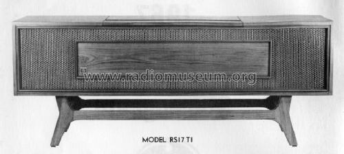
Sign In
Vintage Radio and Television is proudly brought to you by an era where things were built with pride and made to last.
DISCLAIMER: Valve radios and televisions contain voltages that can deliver lethal shocks. You should not attempt to work on a valve radio or other electrical appliances unless you know exactly what you are doing and have gained some experience with electronics and working around high voltages. The owner, administrators and staff of Vintage Radio & Television will accept no liability for any damage, injury or loss of life that comes as a result of your use or mis-use of information on this website. Please read our Safety Warning before using this website.
WARNING: Under no circumstances should you ever apply power to a vintage radio, television or other electrical appliance you have acquired without first having it checked and serviced by an experienced person. Also, at no time should any appliance be connected to an electricity supply if the power cord is damaged. If in doubt, do not apply power.
Shintara - Keepin' It Real · VileSilencer - Maintain The Rage