
Vintage Television
Forum home - Go back to Vintage Television
|
Kriesler 25 Hi Fiette Super F Television information request
|
|
|
Return to top of page · Post #: 1 · Written at 1:54:46 PM on 17 December 2025.
|
|
|
|
Location: Bunbury, WA
Member since 16 December 2025 Member #: 2756 Postcount: 4 |
|
Hello Gents, new to forum. I've picked up a beautiful survivor Kriesler set. (I've sent the page admin the photos to add to the post) 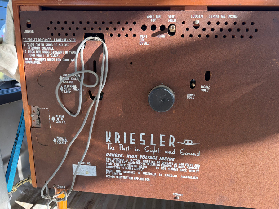 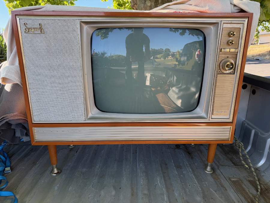 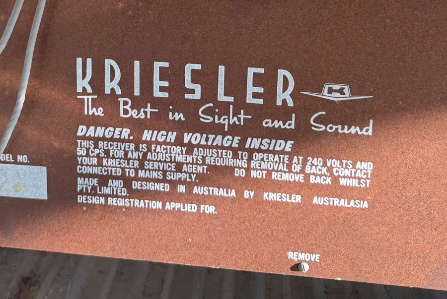 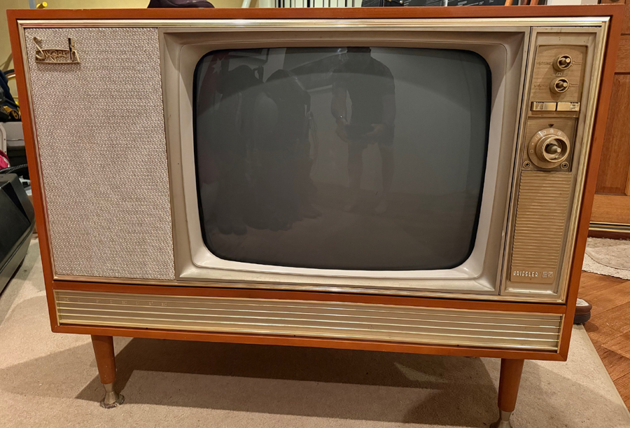 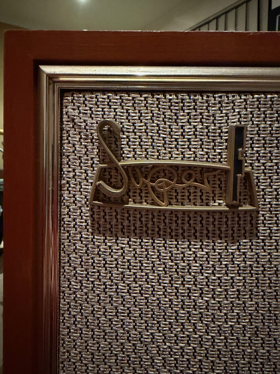 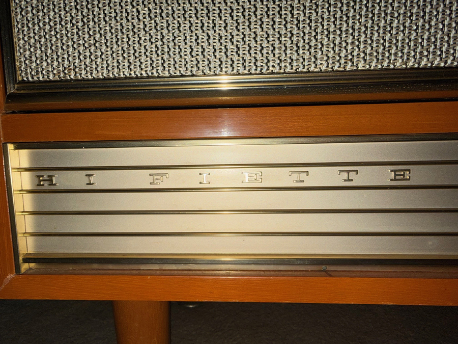 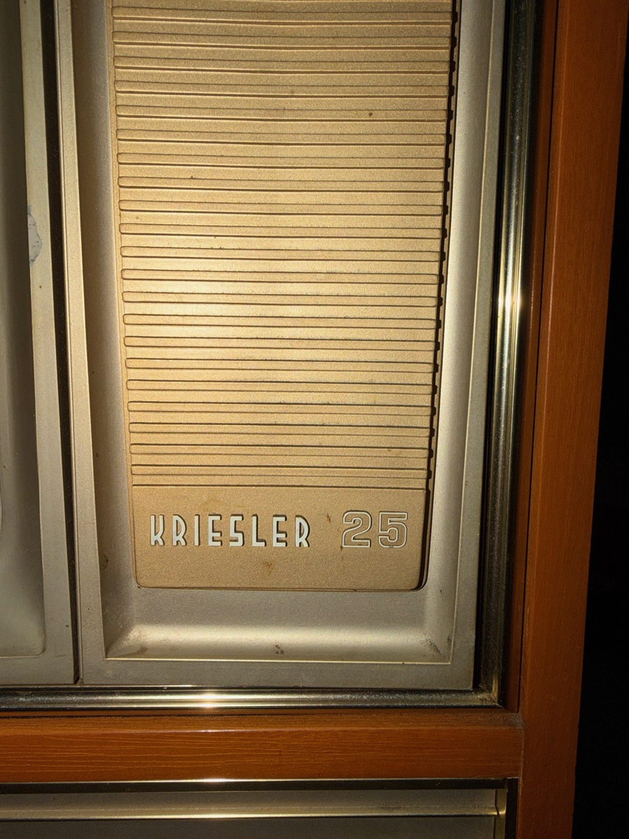 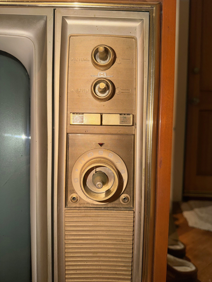 |
|
|
Return to top of page · Post #: 2 · Written at 7:32:47 PM on 17 December 2025.
|
|
|
|
Location: Belrose, NSW
Member since 31 December 2015 Member #: 1844 Postcount: 2689 |
|
Welcome to the hobby that only crazy people indulge in! |
|
|
Return to top of page · Post #: 3 · Written at 8:10:25 PM on 17 December 2025.
|
|

|
Location: Nuriootpa, SA
Member since 28 June 2025 Member #: 2734 Postcount: 66 |
|
Ducons and they generally respond well to a gentle reawakening using a dim bulb |
|
|
Return to top of page · Post #: 4 · Written at 10:12:47 PM on 17 December 2025.
|
|
|
|
Location: Bunbury, WA
Member since 16 December 2025 Member #: 2756 Postcount: 4 |
|
79-15 |
|
|
Return to top of page · Post #: 5 · Written at 11:34:13 PM on 17 December 2025.
|
|

|
Location: Wangaratta, VIC
Member since 21 February 2009 Member #: 438 Postcount: 5687 |
|
The 525V old red Ducons rarely, if ever rejuvenate and it seems to be forgotten on something not used for ages, all of the electrolytics will lose form & fail. |
|
|
Return to top of page · Post #: 6 · Written at 7:24:17 AM on 18 December 2025.
|
|

|
Location: Hobart, TAS
Member since 31 July 2016 Member #: 1959 Postcount: 596 |
|
No red Ducons in Kriesler TV's. |
|
|
Return to top of page · Post #: 7 · Written at 9:08:41 AM on 18 December 2025.
|
|
|
|
Location: Wangaratta, VIC
Member since 21 February 2009 Member #: 438 Postcount: 5687 |
|
The point is that it does not matter how old the electrolytic is. As long as its been neglected for over around two years, even new in storage, it can fail as its chemical and will lose "Form" (Polarity) and can present as a short. |
|
|
Return to top of page · Post #: 8 · Written at 2:13:24 PM on 18 December 2025.
|
|
|
|
Location: Bunbury, WA
Member since 16 December 2025 Member #: 2756 Postcount: 4 |
|
I have use a dim bulb tester with an incandescent 100watt bulb when powering up recently a TEAC AG-6500 receiver, after I replaced the diodes that formed the bridge rectifier, that had blown. Ian mentioned that there was a proven way to bring some life back into the set. I do not have a variac or anyway currently to introduce voltage slowly....Im assuming on would be a good investment? |
|
|
Return to top of page · Post #: 9 · Written at 2:39:05 PM on 18 December 2025.
|
|
|
|
Location: Nuriootpa, SA
Member since 28 June 2025 Member #: 2734 Postcount: 66 |
|
IMO variacs are a bit of a waste of money. |
|
|
Return to top of page · Post #: 10 · Written at 6:06:58 PM on 18 December 2025.
|
|
|
|
Location: Belrose, NSW
Member since 31 December 2015 Member #: 1844 Postcount: 2689 |
|
The big advantage of a dim bulb is, if a fault appears, it will kill the power much quicker than you can react and it will do it while you are not in the room! |
|
|
Return to top of page · Post #: 11 · Written at 6:14:58 PM on 18 December 2025.
|
|
|
|
Location: Hobart, TAS
Member since 31 July 2016 Member #: 1959 Postcount: 596 |
|
I have two variacs and over the past 60 plus years doing these repairs full time have very rarely used one. |
|
|
Return to top of page · Post #: 12 · Written at 7:19:32 PM on 18 December 2025.
|
|
|
|
Location: Belrose, NSW
Member since 31 December 2015 Member #: 1844 Postcount: 2689 |
|
I've sent Brad a copy of the schematic. |
|
|
Return to top of page · Post #: 13 · Written at 9:34:04 PM on 18 December 2025.
|
|
|
|
Location: Wangaratta, VIC
Member since 21 February 2009 Member #: 438 Postcount: 5687 |
|
With radios, for decades I rarely use a Variac and have never used a dim bulb in probably 50 years. |
|
|
Return to top of page · Post #: 14 · Written at 5:23:57 AM on 19 December 2025.
|
|

|
Administrator
Location: Naremburn, NSW
Member since 15 November 2005 Member #: 1 Postcount: 7611 |
|
Photos uploaded. ‾‾‾‾‾‾‾‾‾‾‾‾‾‾‾‾‾‾‾‾‾‾‾‾‾‾‾‾‾‾‾‾‾‾‾‾‾‾‾‾‾‾‾‾‾‾‾‾‾‾‾‾‾‾‾‾‾‾‾‾‾‾‾‾‾‾‾‾ A valve a day keeps the transistor away... |
|
|
Return to top of page · Post #: 15 · Written at 9:36:18 AM on 19 December 2025.
|
|
|
|
Location: Hobart, TAS
Member since 31 July 2016 Member #: 1959 Postcount: 596 |
|
One of the problems I have experienced with the 79-15 is the reversing contacts of the tuner motor (yes, cord remote). |
|
|
You need to be a member to post comments on this forum.
|
|
Sign In
Vintage Radio and Television is proudly brought to you by an era where things were built with pride and made to last.
DISCLAIMER: Valve radios and televisions contain voltages that can deliver lethal shocks. You should not attempt to work on a valve radio or other electrical appliances unless you know exactly what you are doing and have gained some experience with electronics and working around high voltages. The owner, administrators and staff of Vintage Radio & Television will accept no liability for any damage, injury or loss of life that comes as a result of your use or mis-use of information on this website. Please read our Safety Warning before using this website.
WARNING: Under no circumstances should you ever apply power to a vintage radio, television or other electrical appliance you have acquired without first having it checked and serviced by an experienced person. Also, at no time should any appliance be connected to an electricity supply if the power cord is damaged. If in doubt, do not apply power.
Shintara - Keepin' It Real · VileSilencer - Maintain The Rage