Welcome to Australia's only Vintage Radio and Television discussion forums. You are not logged in. Please log in below, apply for an account or retrieve your password.
Australian Vintage Radio Forums
  Home  ·  About Us  ·  Discussion Forums  ·  Glossary  ·  Outside Links  ·  Policies  ·  Services Directory  ·  Safety Warnings  ·  Tutorials

Vintage Television

Forum home - Go back to Vintage Television

 HMV Ambassador B6313 console TV
« Back · 1 · 2 · Next »
 Return to top of page · Post #: 1 · Written at 11:43:08 PM on 7 October 2022.
Rafferty's Gravatar
 Location: Adelaide, SA
 Member since 7 October 2022
 Member #: 2520
 Postcount: 6

Hi Folks,

Have been gifted an Ambassador B6313 console television. A great big beast of a thing.

Before powering it up I inspected the mainboard and discovered a capacitor had been ripped from it so replaced that with a higher voltage one from Jaycar as that is all they had.

Cleaned the front controls with isopropyl just for the time being. Ran it for an few hours or so displaying "chinese rice fights" to see if it was stable.

Buzzing sound coming from speakers when turning the volume up with no audio signal.

Found a $10 vcr to use as a RF converter and plugged an old xbox console into it to test.

Buzzing sound seems to correspond to picture image instability. Flickering and lines which look like VCR tracking lines. Also am having trouble getting a clear image through RF seems like it has a background of static.

After this intial test I have pulled the entire board and mapped all connectors to clean and probably replace more caps. I'd rather not "shotgun" the board as some of these electrolytics are probably better spec than Jaycars brand new ones after 40 years in service.

Question. Does anybody have a service manual for this chassis or model.

Or any tips on what to look out for? This tele looks like it has had the tube replaced and also some work done to it as there are jumper wires and components all over back the board. Just want to replace the usual suspects.

"If it ain"t broke don't fix it"

It works ok. I just want to get a stable picture and sound to watch old Dr Who episodes and play some Mario.

Audio noise

https://youtube.com/shorts/nw19u2J9A2Q?feature=share

Picture noise.

https://youtu.be/G3HqQlkE7tQ

Thanks ahead.

Look forward to your help.

Kindest Regards

P.S I am always discharging the fly back lead to ground with large screwdriver and alligator clips before doing anything within this unit.

HMV Ambassador TV chassis


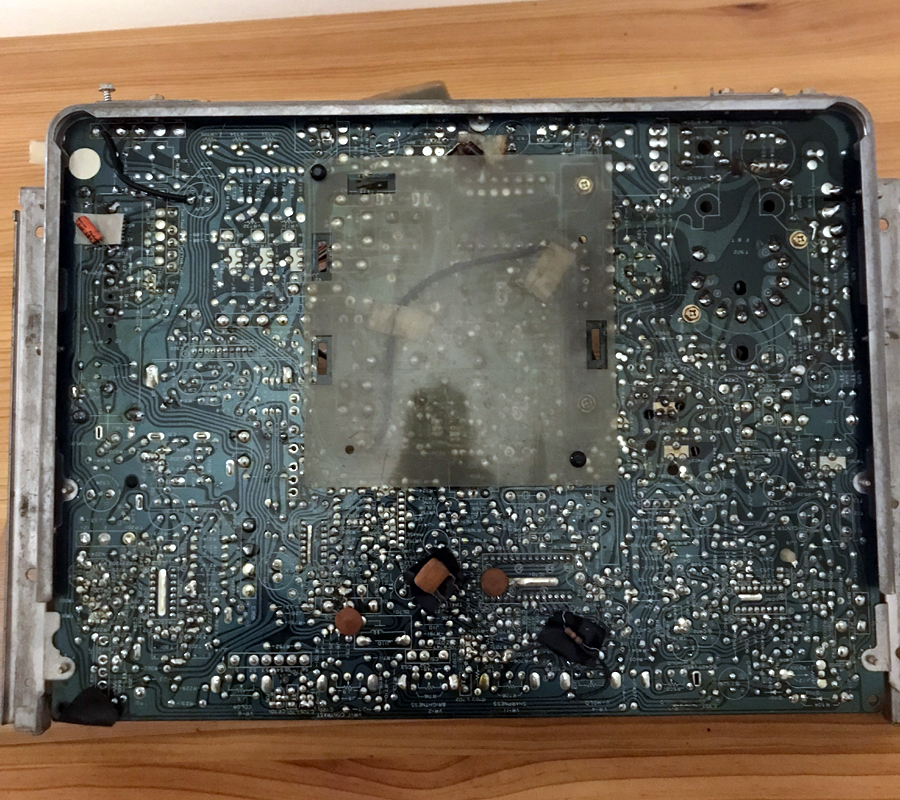
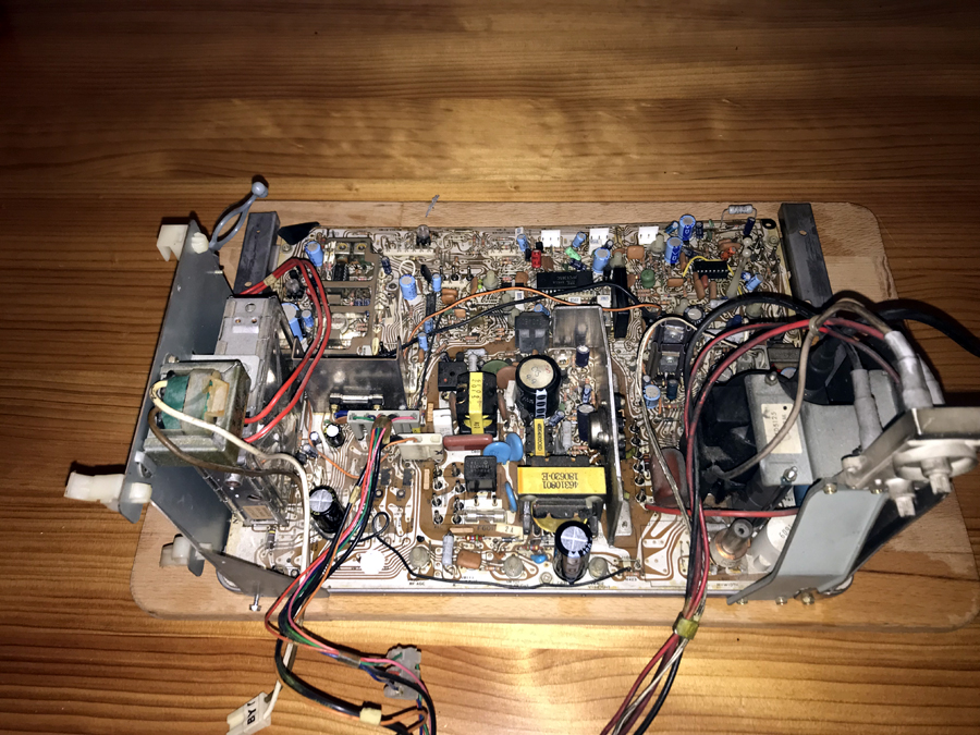
 Return to top of page · Post #: 2 · Written at 4:52:24 AM on 8 October 2022.
Robbbert's avatar
 Location: Hill Top, NSW
 Member since 18 September 2015
 Member #: 1801
 Postcount: 2017

The first video link doesn't work, I got a bunch of other random videos instead.

The 2nd one was too short to make out any problem. The TV looks like it's mostly working though.


 Return to top of page · Post #: 3 · Written at 5:29:44 PM on 9 October 2022.
Ian Robertson's Gravatar
 Location: Belrose, NSW
 Member since 31 December 2015
 Member #: 1844
 Postcount: 2372

The model number you've given us is a cabinet style. What would be more useful is a chassis number.

It will be something like "PU-AF", or "PT-N3". It will be an ink stamp on the chassis.

Does the chassis fold down, or hinge out like a door?

If it's post 1963 or thereabouts (I'll know this from the chassis number) it will have polyester caps and there is no need to replace these.

These sets are a little complex but capable of very good results when in good order.


 Return to top of page · Post #: 4 · Written at 8:02:35 PM on 9 October 2022.
Brad's avatar
 Administrator
 Location: Naremburn, NSW
 Member since 15 November 2005
 Member #: 1
 Postcount: 7307

Photos uploaded.

The first link works as intended. Youtube has this annoying new feature called "Shorts" which is a page with dozens of videos of usually less than a minute jammed into a mobile phone graphic which makes them hard to watch.

In this case, only the audio is relevant though.


‾‾‾‾‾‾‾‾‾‾‾‾‾‾‾‾‾‾‾‾‾‾‾‾‾‾‾‾‾‾‾‾‾‾‾‾‾‾‾‾‾‾‾‾‾‾‾‾‾‾‾‾‾‾‾‾‾‾‾‾‾‾‾‾‾‾‾‾
A valve a day keeps the transistor away...

 
 Return to top of page · Post #: 5 · Written at 10:00:30 PM on 9 October 2022.
Rafferty's Gravatar
 Location: Adelaide, SA
 Member since 7 October 2022
 Member #: 2520
 Postcount: 6

Hi folks,

Sorry about my bad video. The the second was just audio from the speaker buzzing.

The chassis slides out.

The chassis number is B-6313 there is a sticker on the fly back transistor heatsink "Chassis b-6313 No. 0067". The console unit was made in 1981 (it is in the database on this site) possibly in the rank/nec factory in Perth. Could it be an off the shelf chassis that has been relabelled?

I got ahead of myself today and replaced a fair few capacitors it made the hum much less in the audio circuit. And the picture is much more stable and clear.

Unfortunately I have lost voltage on the green drive from the chassis to the neckboard. Red and blue are fine at around 2.1v. If anybody can help me find a schematic for this chassis or identify it that would be greatly appreciated.

I'll be pulling it out again in the next few days as it takes considerable time. Tracing the green circuit back and testing components.

Really need a schematic.

Thankyou ahead


Kindest regards.


 Return to top of page · Post #: 6 · Written at 7:20:24 PM on 11 October 2022.
Labrat's avatar
 Location: Penrith, NSW
 Member since 7 April 2012
 Member #: 1128
 Postcount: 374

Hi all.
I thought that I knew which chassis it was before the picture was published.
I thought it was the N.E.C. chassis with the 1066 (battle of Hastings) board. I was right, and have since found a Rank Arena service manual with rank, and Healing listed on the cover.

I have the full schematic for this model.

I have worked on a number of these in the past, and did not particularly like them. Some like a model, some are indifferent, and some do not like. I particularly remember some trouble with the multi-vibrator in the power supply. Danger. Power supply is live. Connected to the mains..

On the weekend, I will take some photos of the schematic to post.
In the meantime, I would look for dry joints on the transistors on the neck board.

Good luck.

Wayne.


 Return to top of page · Post #: 7 · Written at 9:45:31 PM on 11 October 2022.
Rafferty's Gravatar
 Location: Adelaide, SA
 Member since 7 October 2022
 Member #: 2520
 Postcount: 6

Thanks Mate,

The power supply has a top and bottom safety cover. (I don't understand why they didn't put the power supply on a separate board.) Hence why I've been reluctant to do any work on it unless I remove it from the unit and discharge the main cap and flyback. It's also impossible to work on in the cabinet as it's so low and leads to frustration..

The neck board isn't receiving a GREEN 2.1v signal from the chassis but was before I changed some caps to try and fix the buzzing noise in audio and corresponding picture noise.

I've measured it at the connector pin on the chassis so it's definitely a chassis fault.

Question. Can I swap the RED or BLUE 2.1v feed from the chassis to the non working GREEN circuit on the neckboard to see if it drives it to rule out any problems with the tube or neck board? All colour wires have been spliced through a terminal connector so I could just quickly swap it. Need advice first.

I love the (battle of Hastings) analogy. Just don't want to turn the unit into a Hiroshima.

Thankyou so much for finding the schematic it will help so much to trace back the circuit on the mainboard. Without destroying myself or the unit.

Thanks Ahead.

Mr. Rafferty


 Return to top of page · Post #: 8 · Written at 4:10:18 PM on 12 October 2022.
Irext's avatar
 Location: Werribee South, VIC
 Member since 30 September 2016
 Member #: 1981
 Postcount: 470

You can swap the cathode leads to the CRT quite safely to isolate the fault.


 Return to top of page · Post #: 9 · Written at 12:33:35 PM on 15 October 2022.
Labrat's avatar
 Location: Penrith, NSW
 Member since 7 April 2012
 Member #: 1128
 Postcount: 374

Schematic sent to Brad.

HMV Ambassador B6313 Circuit Diagram


 Return to top of page · Post #: 10 · Written at 7:35:14 PM on 15 October 2022.
Ian Robertson's Gravatar
 Location: Belrose, NSW
 Member since 31 December 2015
 Member #: 1844
 Postcount: 2372

MUCH newer than I was thinking!!

Yes it's an NEC.


 Return to top of page · Post #: 11 · Written at 8:00:04 PM on 15 October 2022.
Rafferty's Gravatar
 Location: Adelaide, SA
 Member since 7 October 2022
 Member #: 2520
 Postcount: 6

Hi all,

Here's a couple of links with more info on the console. It's branded HMV but the Healing brand from the schematic you have tells me it was possibly put together in Sydney? I was incorrect thinking it was the Rank Arena factory.

If it is a NEC board my hunch was correct that they where imported to most companies in Australia.Then botched together so to speak. Hence all some of the factory jumpers all over the board.

Really enjoying learning about long passed electronics manufacture in Australia.

Links:

https://vintage-radio.com.au/default.asp?f=6&th=104

https://www.radiomuseum.org/r/hismasters_ambassador_b6310.html

Kindest Regards

Rafferty


 Return to top of page · Post #: 12 · Written at 9:03:01 PM on 15 October 2022.
Ian Robertson's Gravatar
 Location: Belrose, NSW
 Member since 31 December 2015
 Member #: 1844
 Postcount: 2372

Early colour TV production in Australia

Rank Arena used to assemble NEC chassis from bare PCBs. They supplied those chassis to HMV at Homebush after they phased out their locally designed chassis.

Other local designs, such as Pye, were more successful and continued in production a lot longer. Pye engineers used to disparagingly refer to HMV's operation as a "Canning factory."

Kriesler made local TV chassis designs based on Philips technology.

Philips made CTV chassis locally, based on Philips Eindhoven designs. In the early stages they also made ICs at Hendon in SA.

Sharp used to assemble boards for their local TV production in Fairfield.

National (Panasonic) assembled TV chassis at Penrith. Sanyo did likewise, in Wodonga I think.

AWA assembled Mitsubishi chassis after their ill-fated British Thorn designed 4KA production ended.

Wires running across PCBs was not unusual in the days of single-sided PCBs.


 Return to top of page · Post #: 13 · Written at 8:59:02 PM on 16 October 2022.
BringBackTheValve's Gravatar
 Location: Linton, VIC
 Member since 30 December 2016
 Member #: 2028
 Postcount: 467

Wodonga's correct. Did my time at Sunshine Tech. School of Radio with three of their apprentices 1975 to 1979.

Sanyo Guthrie was their employer. One lived in Wodonga, one in Echuca and the other in "Wang" (slang for Wangaratta)

Much later something happened and the region became known as Albury Wodonga. Now it's Wodonga again. Weird, weirder, weirdest.

I blame climate change, of course---either that or dickhead council execs. with too much time on their hands.


 Return to top of page · Post #: 14 · Written at 8:42:59 PM on 18 October 2022.
Brad's avatar
 Administrator
 Location: Naremburn, NSW
 Member since 15 November 2005
 Member #: 1
 Postcount: 7307

Document uploaded to Post 9.


‾‾‾‾‾‾‾‾‾‾‾‾‾‾‾‾‾‾‾‾‾‾‾‾‾‾‾‾‾‾‾‾‾‾‾‾‾‾‾‾‾‾‾‾‾‾‾‾‾‾‾‾‾‾‾‾‾‾‾‾‾‾‾‾‾‾‾‾
A valve a day keeps the transistor away...

 
 Return to top of page · Post #: 15 · Written at 4:14:38 PM on 27 October 2022.
Irext's avatar
 Location: Werribee South, VIC
 Member since 30 September 2016
 Member #: 1981
 Postcount: 470

I did my time as a radio tradesman apprentice at Sunshine tech during that period also. We were probably in the same classes!.


« Back · 1 · 2 · Next »
 You need to be a member to post comments on this forum.

Sign In

Username:
Password:
 Keep me logged in.
Do not tick box on a computer with public access.