
Vintage Television
Forum home - Go back to Vintage Television
|
Tele-tales. Part 1
|
|
|
Return to top of page · Post #: 1 · Written at 3:17:22 PM on 9 January 2022.
|
|

|
Location: Penrith, NSW
Member since 7 April 2012 Member #: 1128 Postcount: 405 |
|
Hi Folks. I have begun the repair of a Kriesler colour television and thought that you might like to come along on the journey. The patient is a 26” Kriesler Model 660-1, fitted with the 59-01 chassis. 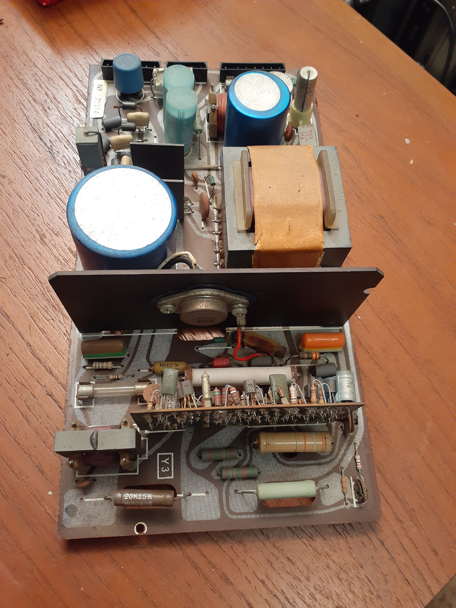   ‾‾‾‾‾‾‾‾‾‾‾‾‾‾‾‾‾‾‾‾‾‾‾‾‾‾‾‾‾‾‾‾‾‾‾‾‾‾‾‾‾‾‾‾‾‾‾‾‾‾‾‾‾‾‾‾‾‾‾‾‾‾‾‾‾‾‾‾ I love the smell of ozone in the morning. |
|
|
Return to top of page · Post #: 2 · Written at 6:50:18 PM on 9 January 2022.
|
|
|
|
Location: Killarney Vale, NSW
Member since 19 March 2012 Member #: 1112 Postcount: 25 |
|
Amazing skills of deduction Warren. You’re a clever man! |
|
|
Return to top of page · Post #: 3 · Written at 10:50:08 AM on 10 January 2022.
|
|
|
|
Location: Linton, VIC
Member since 30 December 2016 Member #: 2028 Postcount: 472 |
|
Hi Labrat. Take a thorough look at the control module for dry joints, especially along the sockets. In fact, re-solder the sockets regardless. |
|
|
Return to top of page · Post #: 4 · Written at 6:08:02 PM on 11 January 2022.
|
|
|
|
Location: Penrith, NSW
Member since 7 April 2012 Member #: 1128 Postcount: 405 |
|
Photos submitted. ‾‾‾‾‾‾‾‾‾‾‾‾‾‾‾‾‾‾‾‾‾‾‾‾‾‾‾‾‾‾‾‾‾‾‾‾‾‾‾‾‾‾‾‾‾‾‾‾‾‾‾‾‾‾‾‾‾‾‾‾‾‾‾‾‾‾‾‾ I love the smell of ozone in the morning. |
|
|
Return to top of page · Post #: 5 · Written at 7:30:05 PM on 11 January 2022.
|
|

|
Administrator
Location: Naremburn, NSW
Member since 15 November 2005 Member #: 1 Postcount: 7614 |
|
Photos uploaded. ‾‾‾‾‾‾‾‾‾‾‾‾‾‾‾‾‾‾‾‾‾‾‾‾‾‾‾‾‾‾‾‾‾‾‾‾‾‾‾‾‾‾‾‾‾‾‾‾‾‾‾‾‾‾‾‾‾‾‾‾‾‾‾‾‾‾‾‾ A valve a day keeps the transistor away... |
|
|
Return to top of page · Post #: 6 · Written at 1:28:18 PM on 13 January 2022.
|
|
|
|
Location: Melbourne, VIC
Member since 5 October 2009 Member #: 555 Postcount: 470 |
|
Hi Wayne, ‾‾‾‾‾‾‾‾‾‾‾‾‾‾‾‾‾‾‾‾‾‾‾‾‾‾‾‾‾‾‾‾‾‾‾‾‾‾‾‾‾‾‾‾‾‾‾‾‾‾‾‾‾‾‾‾‾‾‾‾‾‾‾‾‾‾‾‾ Cheers, Ian |
|
|
Return to top of page · Post #: 7 · Written at 7:50:45 PM on 14 January 2022.
|
|
|
|
Location: Penrith, NSW
Member since 7 April 2012 Member #: 1128 Postcount: 405 |
|
Hi Ian. ‾‾‾‾‾‾‾‾‾‾‾‾‾‾‾‾‾‾‾‾‾‾‾‾‾‾‾‾‾‾‾‾‾‾‾‾‾‾‾‾‾‾‾‾‾‾‾‾‾‾‾‾‾‾‾‾‾‾‾‾‾‾‾‾‾‾‾‾ I love the smell of ozone in the morning. |
|
|
Return to top of page · Post #: 8 · Written at 10:28:55 AM on 15 January 2022.
|
|
|
|
Location: Melbourne, VIC
Member since 5 October 2009 Member #: 555 Postcount: 470 |
|
Hi Wayne, ‾‾‾‾‾‾‾‾‾‾‾‾‾‾‾‾‾‾‾‾‾‾‾‾‾‾‾‾‾‾‾‾‾‾‾‾‾‾‾‾‾‾‾‾‾‾‾‾‾‾‾‾‾‾‾‾‾‾‾‾‾‾‾‾‾‾‾‾ Cheers, Ian |
|
|
Return to top of page · Post #: 9 · Written at 9:43:43 AM on 18 January 2022.
|
|
|
|
Location: Melbourne, VIC
Member since 5 October 2009 Member #: 555 Postcount: 470 |
|
Hi Wayne, ‾‾‾‾‾‾‾‾‾‾‾‾‾‾‾‾‾‾‾‾‾‾‾‾‾‾‾‾‾‾‾‾‾‾‾‾‾‾‾‾‾‾‾‾‾‾‾‾‾‾‾‾‾‾‾‾‾‾‾‾‾‾‾‾‾‾‾‾ Cheers, Ian |
|
|
Return to top of page · Post #: 10 · Written at 7:00:00 PM on 21 January 2022.
|
|
|
|
Location: Belrose, NSW
Member since 31 December 2015 Member #: 1844 Postcount: 2702 |
|
Kriesler put a lot of effort into the service manuals and training. They had to, the TV was a complex but also a well developed design. |
|
|
Return to top of page · Post #: 11 · Written at 5:42:11 PM on 23 January 2022.
|
|
|
|
Location: Penrith, NSW
Member since 7 April 2012 Member #: 1128 Postcount: 405 |
|
Teletales Part two. ‾‾‾‾‾‾‾‾‾‾‾‾‾‾‾‾‾‾‾‾‾‾‾‾‾‾‾‾‾‾‾‾‾‾‾‾‾‾‾‾‾‾‾‾‾‾‾‾‾‾‾‾‾‾‾‾‾‾‾‾‾‾‾‾‾‾‾‾ I love the smell of ozone in the morning. |
|
|
Return to top of page · Post #: 12 · Written at 6:57:59 PM on 23 January 2022.
|
|
|
|
Location: Killarney Vale, NSW
Member since 19 March 2012 Member #: 1112 Postcount: 25 |
|
Wow! It’s one thing after another. I hope the picture tube stays good after the boost. I guess time will tell! Good to know it seems as though it’s had little use so this may be on our side. |
|
|
Return to top of page · Post #: 13 · Written at 8:28:25 PM on 25 January 2022.
|
|
|
|
Location: Belrose, NSW
Member since 31 December 2015 Member #: 1844 Postcount: 2702 |
|
Given normal operating conditions those Philips CRTs normally last well. |
|
|
Return to top of page · Post #: 14 · Written at 4:34:17 PM on 6 February 2022.
|
|
|
|
Location: Penrith, NSW
Member since 7 April 2012 Member #: 1128 Postcount: 405 |
|
Tele-tales Part No.3  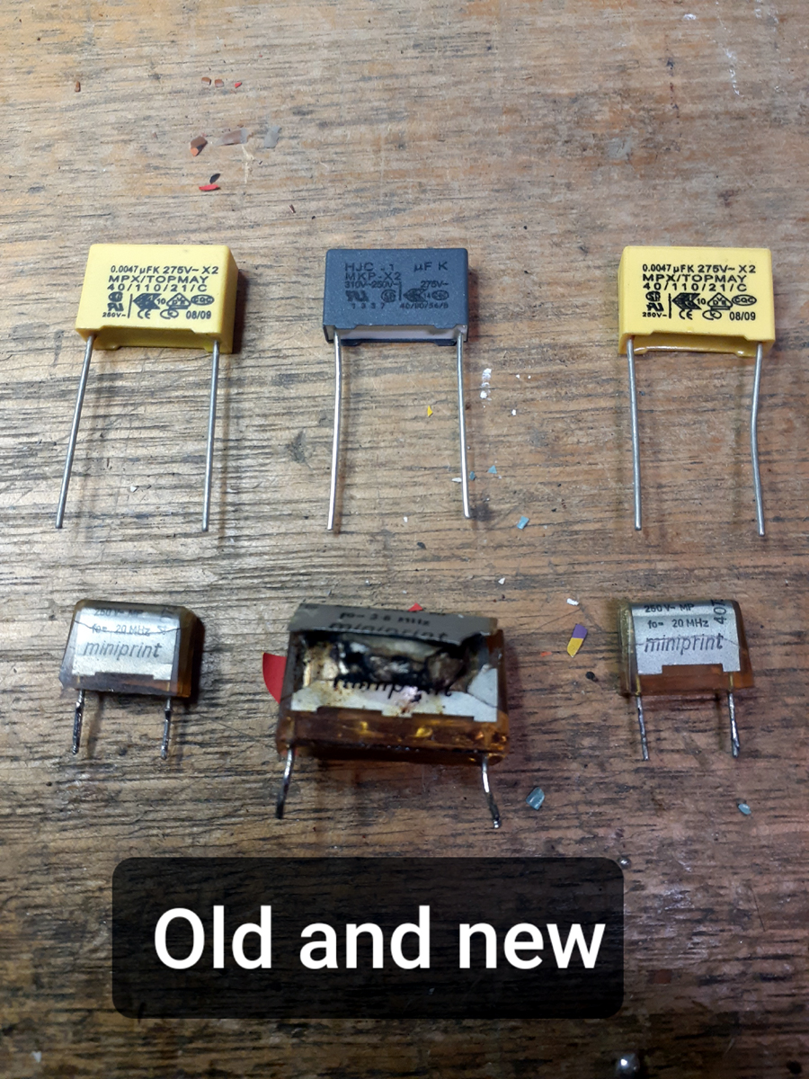 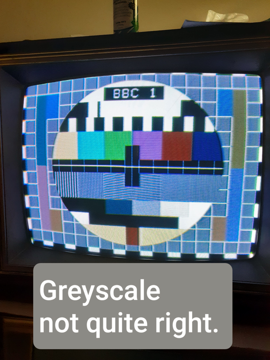 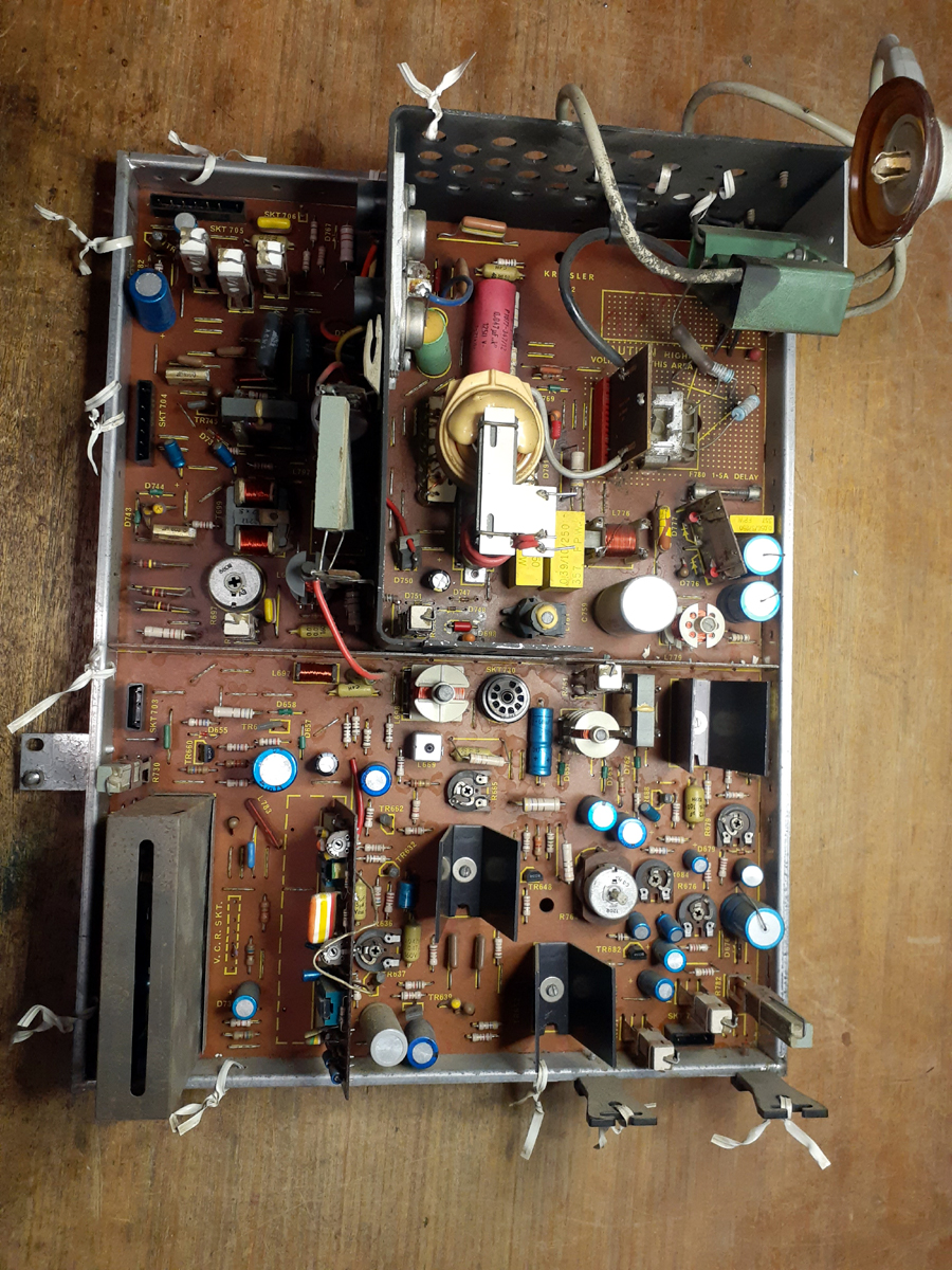  Thank you for following this restoration. Wayne. ‾‾‾‾‾‾‾‾‾‾‾‾‾‾‾‾‾‾‾‾‾‾‾‾‾‾‾‾‾‾‾‾‾‾‾‾‾‾‾‾‾‾‾‾‾‾‾‾‾‾‾‾‾‾‾‾‾‾‾‾‾‾‾‾‾‾‾‾ I love the smell of ozone in the morning. |
|
|
Return to top of page · Post #: 15 · Written at 11:15:12 AM on 7 February 2022.
|
|
|
|
Location: Killarney Vale, NSW
Member since 19 March 2012 Member #: 1112 Postcount: 25 |
|
Hi Wayne |
|
|
You need to be a member to post comments on this forum.
|
|

Sign In
Vintage Radio and Television is proudly brought to you by an era where things were built with pride and made to last.
DISCLAIMER: Valve radios and televisions contain voltages that can deliver lethal shocks. You should not attempt to work on a valve radio or other electrical appliances unless you know exactly what you are doing and have gained some experience with electronics and working around high voltages. The owner, administrators and staff of Vintage Radio & Television will accept no liability for any damage, injury or loss of life that comes as a result of your use or mis-use of information on this website. Please read our Safety Warning before using this website.
WARNING: Under no circumstances should you ever apply power to a vintage radio, television or other electrical appliance you have acquired without first having it checked and serviced by an experienced person. Also, at no time should any appliance be connected to an electricity supply if the power cord is damaged. If in doubt, do not apply power.
Shintara - Keepin' It Real · VileSilencer - Maintain The Rage