Welcome to Australia's only Vintage Radio and Television discussion forums. You are not logged in. Please log in below, apply for an account or retrieve your password.
Australian Vintage Radio Forums
  Home  ·  About Us  ·  Discussion Forums  ·  Glossary  ·  Outside Links  ·  Policies  ·  Services Directory  ·  Safety Warnings  ·  Tutorials

Vintage Television

Forum home - Go back to Vintage Television

 AWA 206CY
« Back · 1 · 2 · 3 · Next »
 Return to top of page · Post #: 1 · Written at 8:08:57 PM on 1 December 2018.
Unknown's Gravatar
 Location: Shepparton, VIC
 Member since 19 June 2011
 Member #: 931
 Postcount: 24

It's been a few years since i've been here, happy to see you are all still here.

I have spent some time out of the hobby as my ex wife did not approve.
Happy to say i'm back now with my first project since 2012.
This one is a real head scratcher, it's an AWA 206CY with vertical collapse, i've recapped the vertical section and rolled some tubes but still have no result.
I have audio and snow somewhat visible as specs in the horizontal line. i'm hoping someone here could give me a few pointers, the set has a full service history and had a brand new Kinescope fitted in 1973, and had frame collapse soon after. It has excellent emission as a low hours tube.
I would love to get it running, and with that in mind I was wondering if someone here has a service manual and circuit diagram, my plan for this set is to put it to use and I was also wondering if someone here could assist with a circuit or idea of how to give it a switched composite video input, switching between composite and the tuner.

Thanks in advance.


 Return to top of page · Post #: 2 · Written at 3:58:12 AM on 2 December 2018.
MonochromeTV's avatar
 Location: Melbourne, VIC
 Member since 20 September 2011
 Member #: 1009
 Postcount: 1179

I can help out with a PDF copy of the service manual.

I am away at the moment so it won’t be until the end of the week.


 Return to top of page · Post #: 3 · Written at 2:39:26 PM on 2 December 2018.
Labrat's avatar
 Location: Penrith, NSW
 Member since 7 April 2012
 Member #: 1128
 Postcount: 368

Just a precaution. Turn the brightness down while working on the set. You don't want to burn a line across the screen.

Good luck.

Wayne.


 Return to top of page · Post #: 4 · Written at 6:51:26 PM on 2 December 2018.
Unknown's Gravatar
 Location: Shepparton, VIC
 Member since 19 June 2011
 Member #: 931
 Postcount: 24

Thanks MonochromeTV.

Way ahead of you Wayne, cut my teeth on VCRs and TV sets from the 90s onwards.


 Return to top of page · Post #: 5 · Written at 8:05:35 AM on 7 December 2018.
Irext's avatar
 Location: Werribee South, VIC
 Member since 30 September 2016
 Member #: 1981
 Postcount: 470

Try briefly connecting via a 1k resistor the heater pin on the Vertical O/P tube to the grid and see if you get any sort of vert deflection. This isolates the fault to either vert osc or vert o/p. Voltage measurements as always are the 1st thing to check. Very low volts on the vert o/p anode could be an o/c vert o/p transformer. Not an uncommon fault on older sets.


 Return to top of page · Post #: 6 · Written at 4:24:38 PM on 28 January 2019.
Unknown's Gravatar
 Location: Shepparton, VIC
 Member since 19 June 2011
 Member #: 931
 Postcount: 24

New year some success,
I found the vertical transformer to be bad, Monochrome TV, I was wondering if you were still willing to send a copy of the service manual to me?

Otherwise I found a corroded wire on the vertical transformer causing the vertical collapse. once repaired I was able to get full deflection with serious linerarity and scan issues, middle of image is wider than top or bottom and no vertical height adjustment to speak of.

I reconditioned the audio stage and have very good audio now, but still am in need of the schematic as the one I am using is very different to this set(from a newer model).

I have injected video into the video amp grid and can get a reasonable picture but the video signal should be 3volts p-p not 1. The tube has excellent emission, but with a low signal input gets washed out if I adjust the brightness too much.

It's turning into a fun project overall.

I plan to fit a composite video and audio input to it using a variation of this :
https://antiqueradio.org/art/RCA_CT-100_Video_Adapter_Plans.jpg Design.

Will continue to update and provide photos if anyone is interested.


 Return to top of page · Post #: 7 · Written at 6:31:15 PM on 28 January 2019.
MonochromeTV's avatar
 Location: Melbourne, VIC
 Member since 20 September 2011
 Member #: 1009
 Postcount: 1179

 
 Return to top of page · Post #: 8 · Written at 9:15:33 PM on 29 January 2019.
Brad's avatar
 Administrator
 Location: Naremburn, NSW
 Member since 15 November 2005
 Member #: 1
 Postcount: 7290

Documents uploaded to Post 7.


‾‾‾‾‾‾‾‾‾‾‾‾‾‾‾‾‾‾‾‾‾‾‾‾‾‾‾‾‾‾‾‾‾‾‾‾‾‾‾‾‾‾‾‾‾‾‾‾‾‾‾‾‾‾‾‾‾‾‾‾‾‾‾‾‾‾‾‾
A valve a day keeps the transistor away...

 
 Return to top of page · Post #: 9 · Written at 1:01:40 PM on 30 January 2019.
Ian Robertson's Gravatar
 Location: Belrose, NSW
 Member since 31 December 2015
 Member #: 1844
 Postcount: 2363

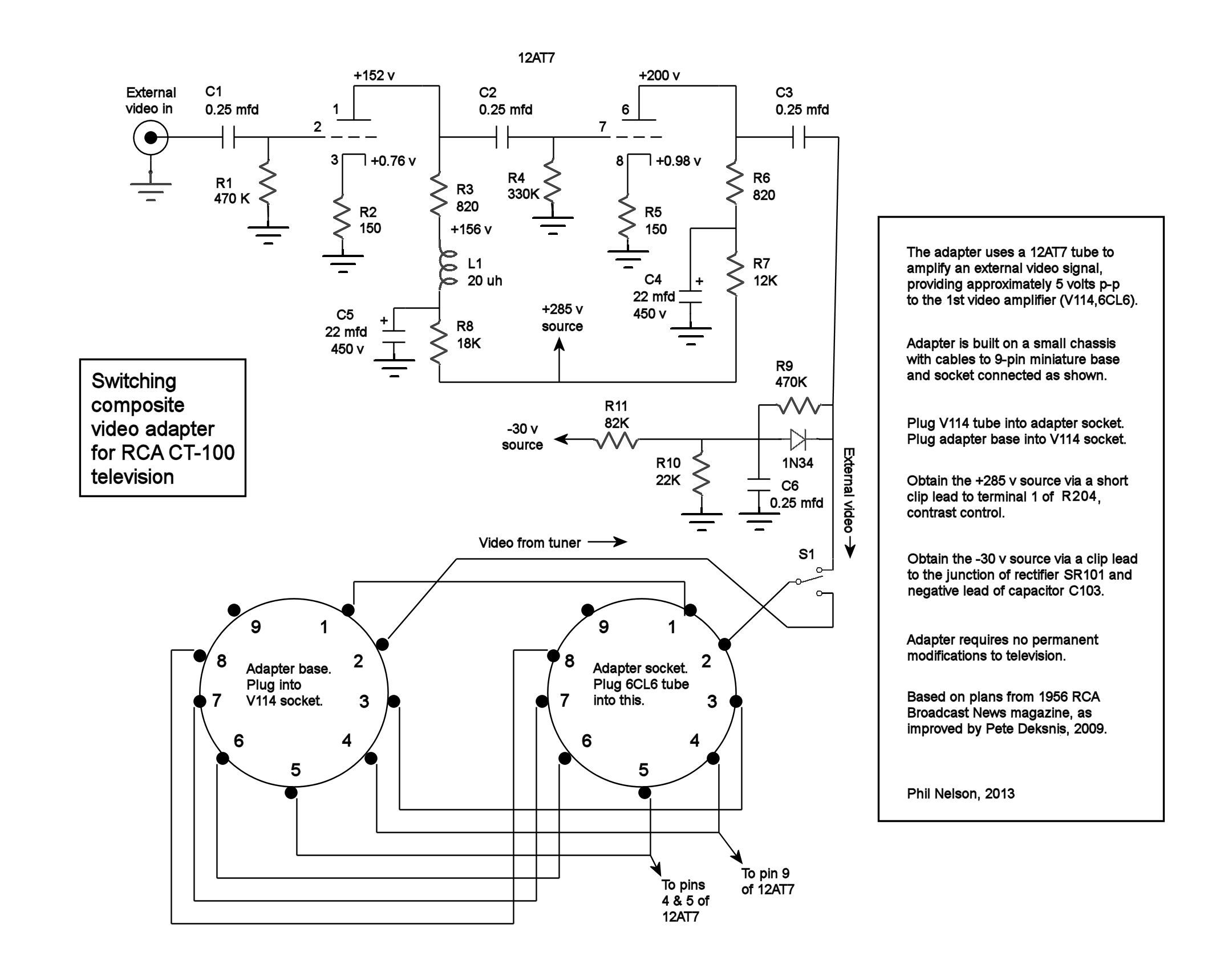
"I plan to fit a composite video and audio input to it using a variation of this :"

No, that's not really suitable, nor does it terminate the video correctly.

Better to use a transistor amp. I lashed one up for the same model AWA when I was doing an initial evaluation. It worked very well. I could probably dig up the circuit if you like.

It's usually not too hard to get such an interface working but it requires engineering skill to get it working properly. Then you have issues with vertical interval signals (e.g. Macrovision) causing white retrace lines that early TV blanking systems can't handle.

I have a preference for using the TV as originally built, which means you'll need a modulator that also solves the blanking and buzz in sound issues. I've posted a design here specifically for vintage TVs. It's been featured in Silicon Chip magazine. They have PCBs and a hard-to-get chip for it.

Your vertical linearity issue will probably be due to off-value resistors and a dried-out cathode bypass cap, which is part of a can electro. In this case you can bypass it with a 100μF 63v cap.

If your can electros are UCCs, they will need replacing. Ducons can usually be re-formed if they are not physically leaking. I have found a good source of can electros if you need them.

My restored AWA is now in a museum.


 Return to top of page · Post #: 10 · Written at 10:21:04 PM on 1 February 2019.
Unknown's Gravatar
 Location: Shepparton, VIC
 Member since 19 June 2011
 Member #: 931
 Postcount: 24

Thanks Monochrome TV, huge relief to finally see what's actually there as opposed to guessing from a 225 schematic.

Ian Robertson, i'm afraid I don't understand what you are trying to say with the video amp, how does it not terminate the video correctly and why would it not work? I have built this and I have a clear, sharp and detailed image with it and a dull one without, (I still have geometry and linearity issues).

If I am feeding a composite signal to the amp and it has no macrovision of any description and no vertical interval signals like your example why would I need to get more complicated?

Thanks for the advice about the caps, I have fully recapped the unit and still have this issue, i'm leaning towards the vertical transformer tr301(vertical oscillator) or the yoke, the yoke matches the 225 chassis but not the 206c (cap is different) and to add insult to injury the yoke has no retainer and mounts differently as well as falling apart and broken plastics I will be remaking unless I can find a yoke to suit the tube(Unlikely).

Again my deepest gratitude for all of your help so far, and sorry for all the questions but I have some gaps in my knowledge so things that might be very obvious to you I have no idea about.


 Return to top of page · Post #: 11 · Written at 10:15:02 AM on 3 February 2019.
Ian Robertson's Gravatar
 Location: Belrose, NSW
 Member since 31 December 2015
 Member #: 1844
 Postcount: 2363

The incoming video should terminate into 75 ohms, i.e. the impedance / resistance measured at the input should be 75 ohms. With a short cable you'll get away with it though. It's just not technically correct.

VERY unlikely to be the blocking oscillator transformer or the yoke. AWA transformers are pretty reliable, I don't recall needing to change any of them in many years of servicing TVs.

Do check the resistor values. Also, some of those caps around the 6AQ5 are critical, you need to use the same value as original. Vertical linearity was never perfect on that circuit, but with correct component values and careful juggling of Height and Linearity it should be not too bad. Do check for O/C or died out cathode bypass on the 6AQ5. That will cause squashing at the bottom. If you try to adjust it out you will squash the top. Very common fault.

The 6AQ5 itself has a fairly easy life in that circuit but if the raster is slow to fill the screen as it warms up you may have a weak one.

The plastic on the yoke rotting away was a common problem with Rola and to a lesser extent MSP yokes. I used a round plastic screw-top food container (like Tupperware) to rebuild a Rola yoke for an HMV F series about a year back.

There is a lot of interchangeability possible with yokes. Just about any MSP or Rola 90 degree yoke will work just fine, you just need to wire it the right way. There are two windings for vertical and two for horizontal scan. On that set both pairs of windings are connected in series. On other TVs (e.g. Philips) they will be in parallel.

If you haven't yet encountered video content with Macrovision encoding, you will! Then you'll know why I went to all that trouble!


 Return to top of page · Post #: 12 · Written at 11:13:02 AM on 3 February 2019.
Irext's avatar
 Location: Werribee South, VIC
 Member since 30 September 2016
 Member #: 1981
 Postcount: 470

If the yoke was at fault you would have severe vertical height problems with keystoning, so very unlikely to be crook (i've never seen one).

Check for O/C linearity pot also. As Ian said vert linearity was never that AWA models strong point but should be acceptable.

The test patterns circle always had a sort of square appearance at best.


 Return to top of page · Post #: 13 · Written at 10:48:50 AM on 16 February 2019.
Unknown's Gravatar
 Location: Shepparton, VIC
 Member since 19 June 2011
 Member #: 931
 Postcount: 24

Thanks everyone for all of your help.
An update and unfortunately the end of the story, I have recapped and replaced all of the resistors in the vertical, horizontal, and agc stages, I have also recapped and replaced most of the parts in the power and boost sections.

After that I still had the same problem just a slightly better picture (better definition).

I went over the scematic, then I got pedantic with resistor and capacitor values to get them within 1% of rating.

No change.

A friend of mine insisted that my composite mod and addition was the issue, so I got the IF sections functioning, bought a 1981 top loader vcr and fed composite that way. I lost a lot of definition and gained snow. but still no change.

I then dug out the trusty IBM Thinkpad with composite and svideo output and fed various resolutions and standards directly and via the IF/VCR to see what would happen.

Running PAL at 640x480 gave a bad image no matter what I did but NTSC gave a bad image with usable vertical.

I left it for a few days to think about it and came back with a 6M5, 6GW8 and a 6W6, I substituted the pentodes for the vertical oscillator and strangely got the identical issue except for the 6M5 which gave a very short image.

The 6M5 was bad. However this showed that the 6AQ5 was not.

after replacing everyting in line with the image, my picture still bloomed, washed out and had no contrast to speak of.
After further research;

I looked at the kinescope. The emitter is black. its a very high hours tube. The service information states a new one was fitted in 1973. that appears to be untrue.

Test Card


 Return to top of page · Post #: 14 · Written at 12:19:59 PM on 16 February 2019.
Ian Robertson's Gravatar
 Location: Belrose, NSW
 Member since 31 December 2015
 Member #: 1844
 Postcount: 2363

When you say "the emiitter is black" do you mean the getter flash, in the neck under the yoke?

Most CRT necks also have an internal graphite coating that connects part of the gun to the final anode.

There is NO way of judging CRT hours by examining the glass. Trust me! On this site you will find a post I made for a method of measuring CRT emission. "How to test a CRT if you don't have a tester" or words to that effect.

When you say the image is "blooming" do you mean the image size increases with brightness?

What is the anode voltage on the 12BY7 video amp?

I'd say that it's quite likely that the CRT WAS actually replaced in 1973.


 Return to top of page · Post #: 15 · Written at 12:54:28 PM on 16 February 2019.
GTC's avatar
 GTC
 Location: Sydney, NSW
 Member since 28 January 2011
 Member #: 823
 Postcount: 6678

On this site you will find a post I made for a method of measuring CRT emission

"Simple emission tester for CRTs in old TVs" here: https://vintage-radio.com.au/home.asp?f=6&th=201


« Back · 1 · 2 · 3 · Next »
 You need to be a member to post comments on this forum.

Sign In

Username:
Password:
 Keep me logged in.
Do not tick box on a computer with public access.