
Vintage Television
Forum home - Go back to Vintage Television
|
What to do if you can't get a part - a case study
|
|
|
« Back ·
1 ·
Next »
|
|
|
Return to top of page · Post #: 1 · Written at 1:55:31 PM on 5 July 2016.
|
|
|
|
Location: Belrose, NSW
Member since 31 December 2015 Member #: 1844 Postcount: 2710 |
|
I'm currently restoring an HMV E1. 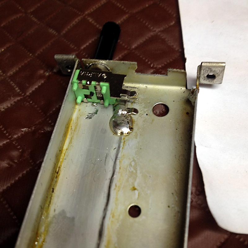 When I found that one winding on the pitch-impregnated original TR3 was open, I first thought we were stuffed! But then, recalling that many TV designs don't use a blocking oscillator transformer, instead running the triode-pentode as an astable with feedback from the pentode anode circuit to the triode grid, I thought this would be worth a try. See the PDF of my modified vertical circuit: HMV E1 Vertical Circuit Diagram What's a little unusual here is the injection of the sync into the grid of the output stage, because the sync is negative-going in the E1. It took a little fiddling with the vertical integrator circuit to get a good solid lock. See the result: 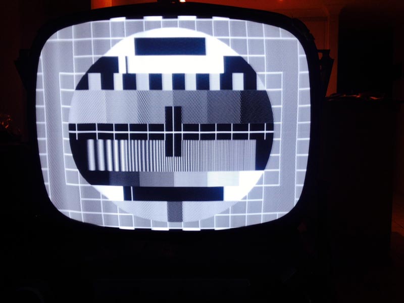 It looks promising, doesn't it? The CRT is a no-ion-trap regun of the original AWV 17HP4B. The aquadag is painted over the original transfer on the glass! Despite tracking down many intermittent faults, replacing all paper caps and many well-out-of-tolerance resistors (a long story for another time) there is still more to do. As with all E1s and E2s, the EHT transformer was replaced very early in the set's life. This one has a Radar part (most were Rolas) and I'm not absolutely sure it is wired correctly. Note the crushing at the 2nd white castellation (this gets much worse if you wind up the width). It is unaffected by the linearity coil setting which effectively functions as a width control. The drive waveforms are (now) spot-on, with many bad parts replaced and a new 6BL8 fitted. Tried new 6CM5 and 6AL3 - no difference. And the "crinkles" on the left hand side - this is the best result obtainable by adjusting the variable cap on the yoke. Does anyone have a copy of the original EHT replacement service bulletin from HMV? Or any clues as to what's going on? |
|
|
Return to top of page · Post #: 2 · Written at 8:11:05 PM on 5 July 2016.
|
|

|
Administrator
Location: Naremburn, NSW
Member since 15 November 2005 Member #: 1 Postcount: 7630 |
|
Files uploaded. ‾‾‾‾‾‾‾‾‾‾‾‾‾‾‾‾‾‾‾‾‾‾‾‾‾‾‾‾‾‾‾‾‾‾‾‾‾‾‾‾‾‾‾‾‾‾‾‾‾‾‾‾‾‾‾‾‾‾‾‾‾‾‾‾‾‾‾‾ A valve a day keeps the transistor away... |
|
|
Return to top of page · Post #: 3 · Written at 8:16:51 PM on 8 July 2016.
|
|
|
|
Location: Ballarat, VIC
Member since 4 January 2011 Member #: 803 Postcount: 456 |
|
HMV released numerous modifications for the E1 chassis which makes any restoration of these sets more difficult than usual. Add the potential for unofficial mods by various repairers over the years, the end result can be a long way from when it left the factory. |
|
|
Return to top of page · Post #: 4 · Written at 1:46:21 PM on 10 July 2016.
|
|
|
|
Location: Belrose, NSW
Member since 31 December 2015 Member #: 1844 Postcount: 2710 |
|
Thanks TV Collector. |
|
|
Return to top of page · Post #: 5 · Written at 8:23:50 PM on 12 July 2016.
|
|
|
|
Location: Ballarat, VIC
Member since 4 January 2011 Member #: 803 Postcount: 456 |
|
I'll get the mod sheets organised for you in the next few days. |
|
|
Return to top of page · Post #: 6 · Written at 11:36:22 AM on 14 July 2016.
|
|
|
|
Location: Belrose, NSW
Member since 31 December 2015 Member #: 1844 Postcount: 2710 |
|
My video source is a Linux based A10 network player box, the PM5544 image is a JPG played by its photo viewer function from a USB thumbdrive. |
|
|
Return to top of page · Post #: 7 · Written at 10:03:44 PM on 17 July 2016.
|
|
|
|
Location: Belrose, NSW
Member since 31 December 2015 Member #: 1844 Postcount: 2710 |
|
Well I think I found it! 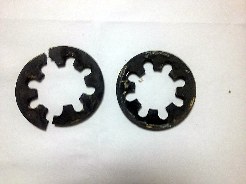 Will try to araldite it back together with minimum possible gap at the break. I'll report back when it's done. |
|
|
« Back ·
1 ·
Next »
|
|
|
You need to be a member to post comments on this forum.
|
|
Sign In
Vintage Radio and Television is proudly brought to you by an era where things were built with pride and made to last.
DISCLAIMER: Valve radios and televisions contain voltages that can deliver lethal shocks. You should not attempt to work on a valve radio or other electrical appliances unless you know exactly what you are doing and have gained some experience with electronics and working around high voltages. The owner, administrators and staff of Vintage Radio & Television will accept no liability for any damage, injury or loss of life that comes as a result of your use or mis-use of information on this website. Please read our Safety Warning before using this website.
WARNING: Under no circumstances should you ever apply power to a vintage radio, television or other electrical appliance you have acquired without first having it checked and serviced by an experienced person. Also, at no time should any appliance be connected to an electricity supply if the power cord is damaged. If in doubt, do not apply power.
Shintara - Keepin' It Real · VileSilencer - Maintain The Rage