
Vintage Television
Forum home - Go back to Vintage Television
|
Fixing vertical blanking deficiencies in old TVs
|
|
|
« Back ·
1 ·
Next »
|
|
|
Return to top of page · Post #: 1 · Written at 2:17:47 PM on 5 June 2016.
|
|
|
|
Location: Belrose, NSW
Member since 31 December 2015 Member #: 1844 Postcount: 2714 |
|
When you run content from DVDs on your retro TV, you may see white diagonal lines near the top of the raster. This happens because much post seventies content includes stuff like time code and test signals in the vertical blanking interval. These signals often run up to peak white level.  The vertical blanking on this TV is a 30v pulse AC coupled to CRT G1 from the secondary of the vertical output transformer. This 30v pulse is much shorter than the vertical blanking interval and does not have enough amplitude to blank a peak white signal. This is not really bad design per se, the TV signals of the day were at black level during the blanking interval so nothing else was needed. How to make the TV compatible with DVD-derived content? I first thought of processing the video prior to the modulator by clipping the video to black level during the vertical blanking interval. Clipping to black would leave the sync unmolested. Doing it this way would also get rid of phantom “caption buzz”. I will probably do this at some stage but for this exercise I wanted the TV to be able to do its own blanking. After trying some passive component ideas, I remembered that early Rank Arena colour TVs had a similar vertical blanking issue caused when teletext was introduced. This was fixed by the addition of a little PCB that contained a 2 transistor monostable to stretch the blanking pulse. So, drawing on this idea but realising my blanking pulses were much higher voltage and negative-going, I designed a mono using two 2N5401 150v PNP transistors and emulated it using LTSpice. The high voltages are needed to completely cut off the CRT via the grid when the cathode approaches 0 volts on peak white. After a little tweaking with the triggering method and the addition of diodes to prevent reverse breakdown of the B-E junctions, here is the circuit and the emulation results. (I needed to use two voltage sources in series to emulate the Kriesler's blanking pulse): 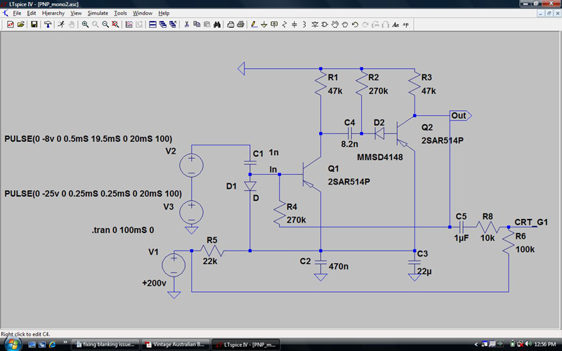 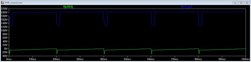 I made this up with real parts, installed it in place of C99 and, after finding that my 2N5401s had pinouts reversed WRT the data sheet and duly reversing them, it worked exactly as emulated. Note that R6 is shown only to emulate the Kriesler's brightness control circuit. C5 is the equivalent to C99 in the TV but had to be made 1μF instead of .22μF because of voltage sag during picture time. The ramp on the original vertical blanking signal neatly compensates for the time constant of C99 and R98, no such possibility now with the “digital” output of the monostable. Here is a close-up of the TV with the height reduced to show the blanking. No more white lines! 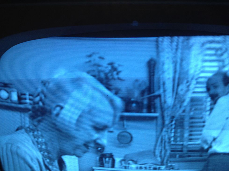 I think this circuit could be adapted to any TV that applies vertical blanking to G1 of the CRT. That's just about all valve B&W TVs. BTW, LTSpice is a free download. Well worth taking the trouble of learning to use it. |
|
|
« Back ·
1 ·
Next »
|
|
|
You need to be a member to post comments on this forum.
|
|
Sign In
Vintage Radio and Television is proudly brought to you by an era where things were built with pride and made to last.
DISCLAIMER: Valve radios and televisions contain voltages that can deliver lethal shocks. You should not attempt to work on a valve radio or other electrical appliances unless you know exactly what you are doing and have gained some experience with electronics and working around high voltages. The owner, administrators and staff of Vintage Radio & Television will accept no liability for any damage, injury or loss of life that comes as a result of your use or mis-use of information on this website. Please read our Safety Warning before using this website.
WARNING: Under no circumstances should you ever apply power to a vintage radio, television or other electrical appliance you have acquired without first having it checked and serviced by an experienced person. Also, at no time should any appliance be connected to an electricity supply if the power cord is damaged. If in doubt, do not apply power.
Shintara - Keepin' It Real · VileSilencer - Maintain The Rage