Welcome to Australia's only Vintage Radio and Television discussion forums. You are not logged in. Please log in below, apply for an account or retrieve your password.
Australian Vintage Radio Forums
  Home  ·  About Us  ·  Discussion Forums  ·  Glossary  ·  Outside Links  ·  Policies  ·  Services Directory  ·  Safety Warnings  ·  Tutorials

Vintage Television

Forum home - Go back to Vintage Television

 Kreisler 79-2/3 chassis
« Back · 1 · Next »
 Return to top of page · Post #: 1 · Written at 1:38:48 PM on 31 December 2015.
Ian Robertson's Gravatar
 Location: Belrose, NSW
 Member since 31 December 2015
 Member #: 1844
 Postcount: 2370

I'm new to this forum but I have a small vintage TV collection - Ekco TX275 portable, AWA 209C and now a Kriesler dating from mid 1959. Cabinet is original, without so much as a scratch. Going by the history card, in November 1970 the set received an overhaul including a new Philips CRT (not a regun, the warranty card is there) and partial recapping. So it looks good for restoration which I'm doing at the moment. I've re-formed the electrolytics and I'm just waiting on a 6AL3 to arrive. Used to be stock-in-trade, the 6AL3! Does anyone know why they always failed cracked glass after rain?

Question is: Does anyone have a schematic of the 79-2/3 chassis? It's not in the JR schematics pdf and the copy glued inside the back is of the 79-2. It seems to be a composite, i.e. basically a 79-2 (90 degree CRT) but with the later NT3001 tuner and the hor. AFC, audio and some other circuits from the 110 degree 79-3. To get the + and - hor reference pulses (taps that don't exist on the 90 degree transformer) a small transformer has been added under the chassis. Looks like they were trying out some new stuff for the forthcoming 110 degree chassis.

I used to repair these things in my first job out of school. I spent 10 years doing TV service 60's - 70's while studying engineering at night.


 Return to top of page · Post #: 2 · Written at 9:28:06 AM on 1 January 2016.
Robbbert's avatar
 Location: Hill Top, NSW
 Member since 18 September 2015
 Member #: 1801
 Postcount: 2014

Good luck with that. I have (or had, maybe) heaps of used 6AL3's.


 Return to top of page · Post #: 3 · Written at 5:36:45 PM on 1 January 2016.
Ian Robertson's Gravatar
 Location: Belrose, NSW
 Member since 31 December 2015
 Member #: 1844
 Postcount: 2370

Sorry guys. I just found the Kriesler schematic well out of sequence in the pdf. It's actually a 79-2 revision 3.

BTW, anyone having difficulty sourcing TV valves, try tubedepot.com. I have a couple of 6CM5s and 6AL3s on the way from them for the Kriesler - from stock. They were able to supply everything I needed for the AWA including some NOS twistlug can electros (these did need reforming though) to replace the crappy, leaking original UCC parts. Mostly NOS tubes, they had Russian 5U4s to replace the 5AS4. They look well made and the one I installed has been working fine for 12 months now. Order on line, you get them in a week or so.

AWAs would have been a much more reliable product if the buyers had spent a bit more money on better quality components. The difference in the Kriesler is noticeable even now.


 Return to top of page · Post #: 4 · Written at 7:49:17 PM on 1 January 2016.
Robbbert's avatar
 Location: Hill Top, NSW
 Member since 18 September 2015
 Member #: 1801
 Postcount: 2014

If I'd known you wanted a 5AS4... I have quite a lot of used ones just taking up space here.

I've come across UCC capacitors before, and in the worst way. Just like Techno capacitors, they are horrible. The Ducon waxed things are great in comparison (and that's not saying much).


 Return to top of page · Post #: 5 · Written at 4:55:13 PM on 4 January 2016.
MonochromeTV's avatar
 Location: Melbourne, VIC
 Member since 20 September 2011
 Member #: 1009
 Postcount: 1182

There are 3 issues of the 79-2 chassis schematics. Issues 1 & 2 has a Philips AT7580 tuner with valves 6CW7 (V6) & 6BL8 (V7). Issue 3 , as mentioned, has the Philips NT3001 tuner with valves 6ES8 (V6) & 6BL8 (V7). In issues 2 & 3 the 1st video IF amp valve (V8) is a 6BY7 instead of a 6BX6. All versions use a 6R3 damper diode.

79-2 issue 2 schematic does not appear in the JR manuals.

Would your TV be one of models shown in the pamphlet at the link below?

Kriesler Magi-Matic Brochure


 Return to top of page · Post #: 6 · Written at 11:23:18 AM on 6 January 2016.
Ian Robertson's Gravatar
 Location: Belrose, NSW
 Member since 31 December 2015
 Member #: 1844
 Postcount: 2370

Thanks Monochrome.

Yes, that is the range, I have the "Future-line Console".
I also have the original user manual if you or anyone else would like a scan of it. Quite amusing when read today!

This set is now cleaned up, recapped and after reforming of the electros overnight worked first go. Looks great. I still have a few minor faults to fix, ratio detector needs to be de-butchered and aligned, the sync is a little weak, vert linearity a bit out - looks like 6BM8 cathode bypass needs replacing and the tuner slugs need a touch-up. CRT was a bit soft when first fired up after 40 years but sharpened up within the first 10 minutes and has been OK since. Not a bad result!


 Return to top of page · Post #: 7 · Written at 12:17:04 PM on 6 January 2016.
MonochromeTV's avatar
 Location: Melbourne, VIC
 Member since 20 September 2011
 Member #: 1009
 Postcount: 1182

Your Future-line Console is a model 121-12A. It is the first of the 79-2 chassis using the NT3001 tuner. There is also a Future-line Console model 121-12AF with a 79-3 chassis and a 110 degree AW53-88 CRT.

Yes I would like a scan of the original user manual. My email contact is visible to other members. In return I have some Kriesler factory manuals, over 60 pages worth, in PDF format for the 79-2 chassis and Model Handbook for models 121-12, 121-13, 121-14 & 121-15.


 Return to top of page · Post #: 8 · Written at 8:50:17 PM on 7 January 2016.
Ian Robertson's Gravatar
 Location: Belrose, NSW
 Member since 31 December 2015
 Member #: 1844
 Postcount: 2370

Hi TV Collector

I'll scan the manual when I'm back in the office next week. My home scanner is no longer supported.....


 Return to top of page · Post #: 9 · Written at 7:23:18 AM on 14 January 2016.
MonochromeTV's avatar
 Location: Melbourne, VIC
 Member since 20 September 2011
 Member #: 1009
 Postcount: 1182

 
 Return to top of page · Post #: 10 · Written at 3:33:36 PM on 3 April 2016.
Ian Robertson's Gravatar
 Location: Belrose, NSW
 Member since 31 December 2015
 Member #: 1844
 Postcount: 2370

Hi All

Well I had this TV running and then - disaster - the EHT overwind broke down and caught fire. Fortunately I was around when it happened but still too late to save it.

What to do? The original (90 degree) transformer was very much unavailable as was the aftermarket replacement (by Radar TV replacements) that was fitted... No-one I could find was capable of rewinding it.

It was a matter of trying to source anything that could be made to work.

A member was able to help with a NOS Philips NT3101A 110 degree transformer. Thank you one and all!!

The circuit this works in is very different but by comparing the 79-2 with the 79-3 I was able to come up with a solution. The .22μF S-correction cap was left out because this is a 90 degree CRT.

And it works!!

The width and EHT are a little high so next step is to get the parts to implement stabilisation as was used with this transformer originally.

After that, I need to stretch the vertical blanking somehow so that DVDs with stuff in the vertical retrace interval don't put junk on the screen.

Kriesler Television


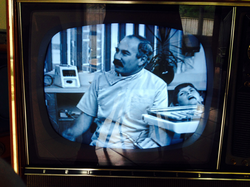
 Return to top of page · Post #: 11 · Written at 4:05:15 PM on 3 April 2016.
Robbbert's avatar
 Location: Hill Top, NSW
 Member since 18 September 2015
 Member #: 1801
 Postcount: 2014

You are extremely lucky you saw that fire before it could burn your house down.

But at least you were able to repair it.


 Return to top of page · Post #: 12 · Written at 7:48:12 PM on 3 April 2016.
Ian Robertson's Gravatar
 Location: Belrose, NSW
 Member since 31 December 2015
 Member #: 1844
 Postcount: 2370

Yeah, well I don't know about that, there wasn't enough flammable material for the fire to catch the cabinet even if it had got that far. Back in the day I saw lots of wax and paper EHT overwind fires (Rola and Precedent transformers come to mind) and the worst effect was a sooty EHT cage. You can see why all plastics used in electrical goods are supposed to contain fire retardants. And the ramifications for a manufacturer if their Chinese contractor decides to cut costs!

Anyway, the replacement transformer is all epoxy insulation. When these fail they get hot, but that's about it.

Oh yes, this brings to mind Pye's transformers that were coated in black "Berry-Wiggins compound". Basically bitumen and wax, that stuff was flammable. But Pyes had a neat thermal fuse in the 6CM5 screen grid. These would pop open as soon as the 6CM5 drew more than about 50% too much current, protecting the valve and avoiding a fire. Colour sets had foldback overcurrent protection but I never knew of a line transformer failure in a Pye colour set. Triplers, yes, but that's a story for another day! As well as why they used that black stuff!


 Return to top of page · Post #: 13 · Written at 4:11:14 PM on 7 April 2016.
Ian Robertson's Gravatar
 Location: Belrose, NSW
 Member since 31 December 2015
 Member #: 1844
 Postcount: 2370

I've since been able to put up a test pattern on the TV.

What that's revealed is, despite the fact I now have the parts to implement stabilisation, I don't think I'll bother now, it's not too bad as it is.

As the pic shows, (thanks Brad!) the image is offset to the left and down. When I centre it, the tube de-focusses very badly and loses brightness. I suspect this is because this tube has an unusually short neck and the old 90 degree Philips yoke (in its aluminium can) is quite deep.So the centering magnets are pulling the electrons over in the wrong part of the gun.

What to do? Well, there are two pre-existing faults that may play out in my favour:

Firstly, the horizontal oscillator only pulls in one way. What I mean is, as you adjust it in one direction, it breaks lock with the picture just floating across the screen. I'm sure this is not as it should be. My guess is if I fix this, the hor phase is more likely to shift the picture to the right.

Secondly, although the vertical linearity looks reasonable, it is slightly stretched at the bottom. Any attempt to adjust this out or increase the height causes worse non-linearity at the top of the raster as the 6BM8 struggles to push the load. The vertical output transformer has been replaced (probably in about 1970) with an aftermarket part. It's possible it's not matching the yoke properly. Screen and cathode resistors check out OK, cathode bypass electro has been replaced - all other electros check out OK. I might have to change the cathode resistor from the original 390 ohm to 330 ohm to make the 6BM8 work harder.

My next step is to make a couple of service position brackets as per the 79-3 so I can have the chassis running while still connected to the CRT and yoke. That should also help me scope out the vertical blanking and come up with a way of stretching it so the time code etc. on some content doesn't show up as white diagonal lines at the top of the raster.

Then there's the sound alignment.

5544 Test Card


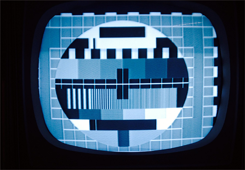
 Return to top of page · Post #: 14 · Written at 4:44:29 PM on 7 April 2016.
Robbbert's avatar
 Location: Hill Top, NSW
 Member since 18 September 2015
 Member #: 1801
 Postcount: 2014

An offset is caused by an incorrect amount of DC flowing through the scan coils (the yoke). Adjusting the AC characteristics (the line frequency) isn't the correct way to fix it.

Vertical non-linearity or cramping could be caused by out of tolerance components in the vertical amplifier, but since parts have been changed it might not be possible to fix it.


 Return to top of page · Post #: 15 · Written at 9:06:34 AM on 8 April 2016.
Ian Robertson's Gravatar
 Location: Belrose, NSW
 Member since 31 December 2015
 Member #: 1844
 Postcount: 2370

Yes Rob but the hor shift issue in this case is caused by the positioning of the pic on the raster. The scan continues (scanning lines light the screen) beyond the edge of the mask. You can shift the picture about 20% with the front panel hor hold control before lock is lost.

No chance of DC in the yoke in this circuit, it's directly connected to the line TX and driven antiphase from what is effectively a centre tapped winding. Nice way to do it, avoids crosstalk to the vertical coils.

Also, the shift issue was there before the old transformer failed....

What I can't remember is if this chassis always locked asymmetrically. I used to work on a lot of these sets 50 years ago, but that's the problem, it was 50 years ago! The service instructions for setting it up are strange to say the least....


« Back · 1 · Next »
 You need to be a member to post comments on this forum.

Sign In

Username:
Password:
 Keep me logged in.
Do not tick box on a computer with public access.